Lexus NX: Visual Mute Signal Circuit between Radio Receiver and Multi-display
DESCRIPTION
The radio receiver assembly sends a visual mute signal to the multi-display assembly. As a result, a black screen is inserted when the screen changes so that noise and distorted images are not displayed.
When an open exists in the circuit, noise and distorted images will be displayed instead of a black screen.
When a short exists in the circuit, even though the multi-display assembly is operating normally, noise and distorted images will be displayed (black screen will not be displayed) during screen changes or the black screen will always be displayed.
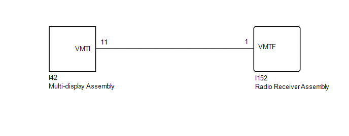
WIRING DIAGRAM
CAUTION / NOTICE / HINT
NOTICE:
- Check that the wire harness is properly installed and does not have any sharp bends, pinching or loose connections.
-
When replacing the radio receiver assembly, always replace it with a new one.
If a radio receiver assembly which was installed to another vehicle is used, the following may occur:
- A communication malfunction DTC may be stored.
- The radio receiver assembly may not operate normally.
HINT:
Depending on the parts that are replaced during vehicle inspection or maintenance, performing initialization, registration or calibration may be needed. Refer to Precaution for Audio and Visual System.
Click here .gif)
PROCEDURE
| 1. | CHECK HARNESS AND CONNECTOR (RADIO RECEIVER ASSEMBLY - MULTI-DISPLAY ASSEMBLY) |
(a) Disconnect the I42 multi-display assembly connector.
(b) Disconnect the I152 radio receiver assembly connector.
(c) Measure the resistance according to the value(s) in the table below.
Standard Resistance:
| Tester Connection | Condition | Specified Condition |
|---|---|---|
| I42-11 (VMTI) - I152-1 (VMTF) | Always | Below 1 Ω |
| I42-11 (VMTI) - Body ground | Always | 10 kΩ or higher |
| NG | .gif) | REPAIR OR REPLACE HARNESS OR CONNECTOR |
|
.gif)
| 2. | CHECK RADIO RECEIVER ASSEMBLY |
| (a) Remove the radio receiver assembly with the connector(s) still connected. |
|
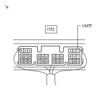
(b) Measure the voltage according to the value(s) in the table below.
Standard Voltage:
| Tester Connection | Switch Condition | Specified Condition |
|---|---|---|
| I152-1 (VMTF) - Body ground | Power switch on (ACC), screen display changes | 3.5 V or higher → Below 1 V → 3.5 V or higher |
| OK | | PROCEED TO NEXT SUSPECTED AREA SHOWN IN PROBLEM SYMPTOMS TABLE |
| NG | | REPLACE RADIO RECEIVER ASSEMBLY |
READ NEXT:
 Radio Receiver Power Source Circuit
DESCRIPTION This is the power source circuit to operate the radio receiver assembly. WIRING DIAGRAM CAUTION / NOTICE / HINT NOTICE:
Inspect the fuses for circuits related to this system before per
Components
COMPONENTS ILLUSTRATION *A w/o Power Back Door *B w/ Power Back Door *C for 10 Speakers *D for 14 Speakers *1 BACK DOOR CENTER GARNISH *2 BACK DOOR FINISH COVER LH *3
SEE MORE:
Part of HV Gate Blocking Range/Performance (P321F-319)
DESCRIPTION Refer to the description for DTC P321E-318. Click here DTC No. Detection Item DTC Detection Condition Trouble Area MIL Warning Indicate P321F-319 Part of HV Gate Blocking Range/Performance An open or ground short in the HV gate block signal circuit when the gate is
Steering Angle Sensor Failure (C1626)
DESCRIPTION This DTC is stored if the parking assist ECU receives a signal via CAN communication from the steering sensor that indicates an internal malfunction. DTC No. Detection Item DTC Detection Condition Trouble Area C1626 Steering Angle Sensor Failure A fail flag is transmitte
