Lexus NX: Volume Switch Circuit (B1361)
DESCRIPTION
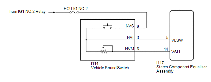
The stereo component equalizer assembly adjusts sound volume based on the signal sent by the vehicle sound switch.
| DTC No. | Detection Item | DTC Detection Condition | Trouble Area |
|---|---|---|---|
| B1361 | Volume Switch Circuit | Open in the volume switch circuit |
|
WIRING DIAGRAM
CAUTION / NOTICE / HINT
NOTICE:
Inspect the fuses for circuits related to this system before performing following procedure.
PROCEDURE
| 1. | READ VALUE USING TECHSTREAM |
(a) Using the Techstream, read the Data List.
Click here .gif)
| Tester Display | Measurement Item | Range | Normal Condition | Diagnostic Note |
|---|---|---|---|---|
| Volume SW | Vehicle sound switch on/off status | OFF or ON | OFF: Vehicle sound switch off ON: Vehicle sound switch on | - |
| Volume Switch Voltage | The VSLI terminal voltage to the CPU of the stereo compartment equalizer assembly | Min.: 0 V Max.: 5 V | Changes according to vehicle sound switch volume setting | - |
| Tester Display |
|---|
| Volume SW |
| Volume Switch Voltage |
OK:
The display is as specified in the normal condition column.
| OK | .gif) | REPLACE STEREO COMPONENT EQUALIZER ASSEMBLY |
|
.gif)
| 2. | INSPECT VEHICLE SOUND SWITCH |
(a) Remove the vehicle sound switch.
Click here
(b) Inspect the vehicle sound switch.
Click here
| NG | | REPLACE VEHICLE SOUND SWITCH |
|
| 3. | CHECK HARNESS AND CONNECTOR (VEHICLE SOUND SWITCH - BATTERY) |
| (a) Disconnect the vehicle sound switch connector. |
|
(b) Measure the voltage according to the value(s) in the table below.
Standard Voltage:
| Tester Connection | Switch Condition | Specified Condition |
|---|---|---|
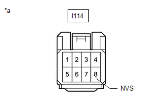
| I114-8 (NVS) - Body ground | Power switch on (IG) | 11 to 14 V |
| I114-8 (NVS) - Body ground | Power switch off | Below 1 V |
| NG | | REPAIR OR REPLACE HARNESS OR CONNECTOR |
|
| 4. | CHECK HARNESS AND CONNECTOR (VEHICLE SOUND SWITCH - STEREO COMPONENT EQUALIZER ASSEMBLY) |
(a) Disconnect the I114 vehicle sound switch connector.
(b) Disconnect the I117 stereo component equalizer assembly connector.
(c) Measure the resistance according to the value(s) in the table below.
Standard Resistance:
| Tester Connection | Condition | Specified Condition |
|---|---|---|
| I114-3 (NVI) - I117-5 (VLSW) | Always | Below 1 Ω |
| I114-6 (NVM) - I117-14 (VSLI) | Always | Below 1 Ω |
| I114-3 (NVI) or I117-5 (VLSW) - Body ground | Always | 10 kΩ or higher |
| I114-6 (NVM) or I117-14 (VSLI) - Body ground | Always | 10 kΩ or higher |
| OK | | REPLACE STEREO COMPONENT EQUALIZER ASSEMBLY |
| NG | | REPAIR OR REPLACE HARNESS OR CONNECTOR |
READ NEXT:
 ECU Malfunction (B1362)
DESCRIPTION This DTC is stored when the stereo component equalizer assembly detects an internal malfunction. DTC No. Detection Item DTC Detection Condition Trouble Area B1362 ECU Malfun
Lost Communication with Brake System Control Module (U0129,U0142,U0293)
DESCRIPTION DTC No. Detection Item DTC Detection Condition Trouble Area U0129 Lost Communication with Brake System Control Module No communication with brake booster with master cylin
Main Switch Circuit
DESCRIPTION The stereo component equalizer assembly detects vehicle sound switch signals. The ASC system can be turned on and off by operating the vehicle sound switch. WIRING DIAGRAM CAUTION / NOTIC
SEE MORE:
On-vehicle Inspection
ON-VEHICLE INSPECTION PROCEDURE 1. VISUALLY INSPECT HOSES, CONNECTIONS AND GASKETS (a) Visually check that the hoses, connections and gaskets have no cracks, leaks or damage. NOTICE:
Detachment or other problems with the engine oil dipstick, oil filler cap sub-assembly, PCV hose and other compone
Removal
REMOVAL CAUTION / NOTICE / HINT HINT:
Use the same procedure for the RH and LH sides.
The procedure listed below is for the LH side.
PROCEDURE 1. REMOVE NO. 3 DECK BOARD SUB-ASSEMBLY Click here 2. REMOVE REAR DECK FLOOR BOX Click here 3. REMOVE DECK FLOOR BOX LH Click here 4. PRECAUTIO
