Lexus NX: On-vehicle Inspection
ON-VEHICLE INSPECTION
PROCEDURE
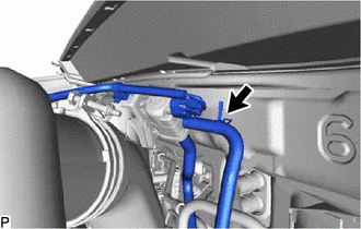
1. VISUALLY INSPECT HOSES, CONNECTIONS AND GASKETS
(a) Visually check that the hoses, connections and gaskets have no cracks, leaks or damage.
NOTICE:
- Detachment or other problems with the engine oil dipstick, oil filler cap sub-assembly, PCV hose and other components may cause the engine to run improperly.
- Disconnection, looseness or cracks in the parts of the air induction system between the throttle body assembly with motor and cylinder head sub-assembly will allow air suction and cause an engine failure or engine malfunctions.
If the result is not as specified, replace parts as necessary.
2. INSPECT EVAPORATIVE EMISSION CONTROL SYSTEM
(a) Connect the Techstream to the DLC3.
(b) Put the engine in inspection mode (maintenance mode)
Click here .gif)
| (c) Slide the clamp and disconnect the fuel vapor feed hose from the purge VSV. |
|
(d) Start the engine.
(e) Enter the following menus: Powertrain / Engine and ECT / Active Test / Activate the VSV for Evap Control.
Powertrain > Engine and ECT > Active Test| Tester Display |
|---|
| Activate the VSV for Evap Control |
(f) Check that vacuum occurs at the purge VSV port.
If vacuum does not occur, check the following items.
- Purge VSV
- Clogging in the fuel vapor feed hose connecting the intake manifold and purge VSV
- Voltage at the ECM PRG terminal
(g) Exit Active Test mode and reconnect the fuel vapor feed hose.
(h) Enter the following menus: Powertrain / Engine and ECT / Data List / EVAP Purge VSV.
Powertrain > Engine and ECT > Data List| Tester Display |
|---|
| EVAP Purge VSV |
(i) Warm up the engine and drive the vehicle.
(j) Confirm that the purge valve opens.
If the result is not as specified, replace the purge VSV, wire harness or ECM.
3. CHECK LINE AND CONNECTORS
(a) Visually check for loose connections, sharp bends or damage.
4. CHECK FUEL TANK ASSEMBLY
(a) Visually check for deformation, cracks or fuel leakage.
5. CHECK FUEL TANK AND VENT LINE
(a) Disconnect the vent line hose from the charcoal canister assembly.
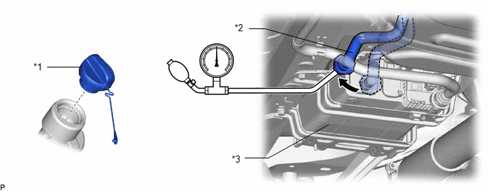
| *1 | Fuel Tank Cap Assembly | *2 | Vent Line Hose |
| *3 | Charcoal Canister Assembly | - | - |
(b) Connect a pressure gauge to the vent line hose.
(c) Apply 4 kPa (0.04 kgf/cm2, 0.6 psi) of pressure to the vent line of the fuel tank assembly.
HINT:
Perform this inspection with the fuel tank assembly less than 90% full. When the fuel tank assembly is full, the fuel cutoff valve closes and pressure is released through the 1.5 mm (0.0591 in.) orifice. As a result, when the fuel tank cap assembly is removed, the pressure does not decrease smoothly.
(d) Check that the fuel tank assembly pressure is maintained for some time, and does not decrease immediately.
HINT:
If the pressure decreases immediately, one of the following may be the cause:
- The fuel tank cap assembly is not completely tightened.
- The fuel tank cap assembly is damaged.
- Air is leaking from the vent line tube.
- The fuel tank assembly is damaged.
(e) When the fuel tank cap assembly is removed, check that pressure is released smoothly.
HINT:
If the pressure does not drop, replace the fuel tank assembly.
(f) Reconnect the vent line hose to the charcoal canister assembly.
6. CHECK AIR INLET LINE
(a) Disconnect the air inlet line hose from the charcoal canister assembly.
(b) Check that air flows freely into the air inlet line.
HINT:
If air does not flow freely into the air inlet line, repair or replace it.
(c) Reconnect the air inlet line hose to the charcoal canister assembly.
READ NEXT:
 Fuel Tank Cap
InspectionINSPECTION PROCEDURE 1. INSPECT FUEL TANK CAP ASSEMBLY (a) Visually check that the fuel tank cap assembly and fuel tank cap gasket are not deformed or damaged. *1 Fuel Tank Cap Gasket
Pcv Valve
ComponentsCOMPONENTS ILLUSTRATION *1 PCV VALVE SUB-ASSEMBLY *2 NO. 2 PCV HOSE N*m (kgf*cm, ft.*lbf): Specified torque Toyota Genuine Adhesive 1324, Three Bond 1324 or equivalent
Purge Valve
ComponentsCOMPONENTS ILLUSTRATION *1 PURGE VSV *2 FUEL VAPOR FEED HOSE *3 NO. 2 FUEL VAPOR FEED HOSE - - RemovalREMOVAL PROCEDURE 1. REMOVE PURGE VSV (a) Disconnect the wir
SEE MORE:
Lost Communication with "Door Control Module B" (U0200)
DESCRIPTION DTC No. Detection Item DTC Detection Condition Trouble Area DTC Output from U0200 Lost Communication with "Door Control Module B" There is no communication from the outer mirror control ECU assembly RH.
Power source circuit of outer mirror control ECU assembly RH
Installation
INSTALLATION CAUTION / NOTICE / HINT HINT:
Use the same procedure for the RH and LH sides.
The procedures listed below are for the LH side.
PROCEDURE 1. INSTALL FRONT DOOR LOWER OUTSIDE MOULDING SUB-ASSEMBLY LH HINT: When installing the front door lower outside moulding sub-assembly LH, heat
