Lexus NX: Wireless Charger Power Source Circuit
DESCRIPTION
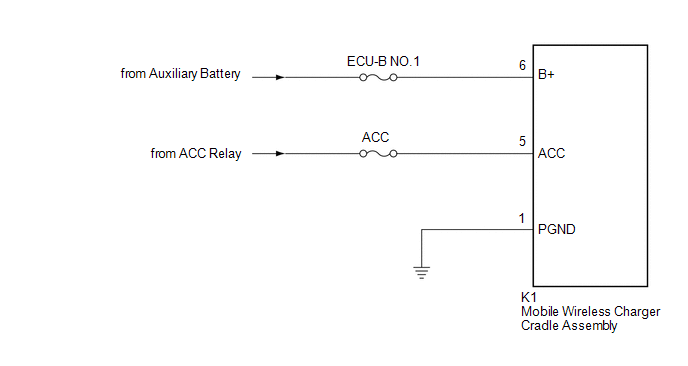
This is the power source circuit to operate the mobile wireless charger cradle assembly.
WIRING DIAGRAM
CAUTION / NOTICE / HINT
NOTICE:
Inspect the fuses for circuits related to this system before performing the following inspection procedure.
PROCEDURE
| 1. | CHECK HARNESS AND CONNECTOR (MOBILE WIRELESS CHARGER CRADLE ASSEMBLY - BATTERY AND BODY GROUND) |
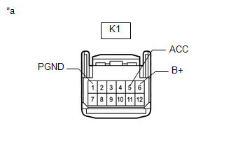
| (a) Disconnect the mobile wireless charger cradle assembly connector. |
|
(b) Measure the resistance according to the value(s) in the table below.
Standard Resistance:
| Tester Connection | Condition | Specified Condition |
|---|---|---|
| K1-1 (PGND) - Body ground | Always | Below 1 Ω |
(c) Measure the voltage according to the value(s) in the table below.
Standard Voltage:
| Tester Connection | Switch Condition | Specified Condition |
|---|---|---|
| K1-6 (B+) - Body ground | Power switch off | 11 to 14 V |
| K1-5 (ACC) - Body ground | Power switch on (ACC) | 11 to 14 V |
| Power switch off | Below 1 V |
| OK | .gif) | PROCEED TO NEXT SUSPECTED AREA SHOWN IN PROBLEM SYMPTOMS TABLE |
| NG | | REPAIR OR REPLACE HARNESS OR CONNECTOR |
READ NEXT:
 Status Signal Circuit
DESCRIPTION This circuit sends a charging stop signal from the certification ECU (smart key ECU assembly) to the mobile wireless charger cradle assembly. Based on this signal, the wireless charging sy
SEE MORE:
ACC Monitor Malfunction (B2274)
DESCRIPTION This DTC is stored when a malfunction in the ACC output circuit is detected. The ACC output circuit is the circuit that goes from the ACC output terminal of the certification ECU (smart key ECU assembly) to the ACC relay. DTC No. Detection Item DTC Detection Condition Trouble Ar
Problem Symptoms Table
PROBLEM SYMPTOMS TABLE HINT:
Use the table below to help determine the cause of problem symptoms. If multiple suspected areas are listed, the potential causes of the symptoms are listed in order of probability in the "Suspected Area" column of the table. Check each symptom by checking the suspect
