Lexus NX: XM Tuner Antenna Disconnected (B15FE,B15FF)
DESCRIPTION
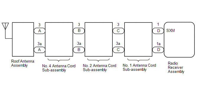
These DTCs are stored when a malfunction occurs in the roof antenna assembly which is connected to the radio receiver assembly.
| DTC No. | Detection Item | DTC Detection Condition | Trouble Area |
|---|---|---|---|
| B15FE | XM Tuner Antenna Disconnected | The roof antenna assembly is not connected. |
|
| B15FF | XM Tuner Antenna Short | A short occurs in the roof antenna assembly. |
|
WIRING DIAGRAM
CAUTION / NOTICE / HINT
NOTICE:
When replacing the radio receiver assembly, always replace it with a new one.
If a radio receiver assembly which was installed to another vehicle is used, the following may occur:
- A communication malfunction DTC may be stored.
- The radio receiver assembly may not operate normally.
HINT:
Depending on the parts that are replaced during vehicle inspection or maintenance, performing initialization, registration or calibration may be needed. Refer to Precaution for Audio and Visual System.
Click here .gif)
PROCEDURE
| 1. | CHECK CONNECTION OF ANTENNA CABLE |
(a) Check if the roof antenna assembly cable is securely connected to the radio receiver assembly.
OK:
Roof antenna assembly cable is securely connected.
| NG | .gif) | SECURELY CONNECT ROOF ANTENNA ASSEMBLY CABLE |
|
.gif)
| 2. | CHECK DTC |
(a) Clear the DTCs.
Click here
(b) Recheck for DTCs and check that no DTCs are output.
Click here
OK:
No DTCs are output.
| OK | | USE SIMULATION METHOD TO CHECK |
|
| 3. | CHECK NO. 4 ANTENNA CORD SUB-ASSEMBLY |
| (a) Disconnect the antenna connector from the roof antenna assembly. |
|
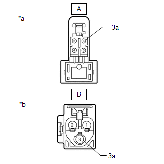
(b) Disconnect the antenna connector from the No. 2 antenna cord sub-assembly.
(c) Measure the resistance according to the value(s) in the table below.
Standard Resistance:
| Tester Connection | Condition | Specified Condition |
|---|---|---|
| A-3 - B-3 | Always | Below 1 Ω |
| A-3a - B-3a | Always | Below 1 Ω |
| A-3 - Body ground | Always | 10 kΩ or higher |
| A-3a - Body ground | Always | 10 kΩ or higher |
| NG | | REPLACE NO. 4 ANTENNA CORD SUB-ASSEMBLY |
|
| 4. | CHECK NO. 2 ANTENNA CORD SUB-ASSEMBLY |
| (a) Disconnect the antenna connector from the No. 4 antenna cord sub-assembly. |
|
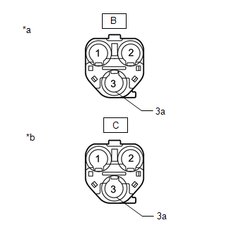
(b) Disconnect the antenna connector from the No. 1 antenna cord sub-assembly.
(c) Measure the resistance according to the value(s) in the table below.
Standard Resistance:
| Tester Connection | Condition | Specified Condition |
|---|---|---|
| B-3 - C-3 | Always | Below 1 Ω |
| B-3a - C-3a | Always | Below 1 Ω |
| B-3 - Body ground | Always | 10 kΩ or higher |
| B-3a - Body ground | Always | 10 kΩ or higher |
| NG | | REPLACE NO. 2 ANTENNA CORD SUB-ASSEMBLY |
|
| 5. | CHECK NO. 1 ANTENNA CORD SUB-ASSEMBLY |
| (a) Disconnect the antenna connector from the No. 2 antenna cord sub-assembly. |
|
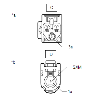
(b) Disconnect the antenna connector from the radio receiver assembly.
(c) Measure the resistance according to the value(s) in the table below.
Standard Resistance:
| Tester Connection | Condition | Specified Condition |
|---|---|---|
| C-3 - D-1 (SXM) | Always | Below 1 Ω |
| C-3a - D-1a | Always | Below 1 Ω |
| C-3 - Body ground | Always | 10 kΩ or higher |
| C-3a - Body ground | Always | 10 kΩ or higher |
| NG | | REPLACE NO. 1 ANTENNA CORD SUB-ASSEMBLY |
|
| 6. | CHECK ROOF ANTENNA ASSEMBLY |
(a) Replace the roof antenna assembly with a new or known good one.
Click here
(b) Clear the DTCs.
Click here
(c) Recheck for DTCs and check that no DTCs are output.
Click here
OK:
No DTCs are output.
| OK | | END (ROOF ANTENNA ASSEMBLY IS DEFECTIVE) |
| NG | | REPLACE RADIO RECEIVER ASSEMBLY |
READ NEXT:
 Back Camera Disconnected (C1622)
DESCRIPTION This DTC is stored if the radio receiver assembly judges that the signals or signal lines between the television camera assembly and the multi-display assembly are not normal as a result o
Sending Malfunction (Navigation to APGS) (U0073,U0100,U0129,U0140,U0155,U0164,U0198,U023B,U0265,U0293,U1110)
DESCRIPTION These DTCs are stored when a malfunction occurs in the CAN communication circuit. DTC No. Detection Item DTC Detection Condition Trouble Area U0073 Sending Malfunction (Navi
Satellite Radio Broadcast cannot be Received
WIRING DIAGRAM CAUTION / NOTICE / HINT NOTICE:
Some satellite radio broadcasts require payment. A contract must be made between a satellite radio company and the user. If the contract expires, it
SEE MORE:
Components
COMPONENTS ILLUSTRATION *A w/o AVS - - *1 FRONT FLEXIBLE HOSE *2 FRONT SHOCK ABSORBER WITH COIL SPRING *3 FRONT SPEED SENSOR LH *4 FRONT STABILIZER LINK ASSEMBLY LH *5 FRONT SUSPENSION SUPPORT DUST COVER LH *6 FRONT SUSPENSION SUPPORT PLATE LH *7 COWL BO
Diagnostic Trouble Code Chart
DIAGNOSTIC TROUBLE CODE CHART CAN Communication System DTC No. Detection Item DTC Output from Link B1003 ECU Malfunction Central gateway ECU (network gateway ECU) U0199 Lost Communication with "Door Control Module A" Main Body U0200 Lost Communication with "D
