Lexus NX: Installation
INSTALLATION
CAUTION / NOTICE / HINT
HINT:
- Use the same procedure for the RH and LH sides.
- The procedure described below is for the LH side.
PROCEDURE
1. INSTALL REAR COMBINATION LIGHT ASSEMBLY LH
| (a) Attach the guide and pin to set the rear combination light assembly LH. |
|
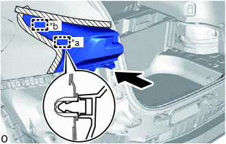
| (b) Install the 3 screws. |
|
.png)
(c) Pass the wire harness into the vehicle and connect the grommet.
(d) Place your hand between the deck trim side panel assembly LH and the body to connect the connector.
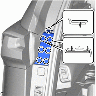
2. INSTALL REAR COMBINATION LIGHT COVER LH
| (a) Attach the 7 claws to install the rear combination light cover LH. |
|
3. CONNECT DECK TRIM SIDE PANEL ASSEMBLY LH
(a) Connect the rear side of the deck trim side panel assembly LH.
Click here .gif)
4. INSTALL NO. 1 LUGGAGE COMPARTMENT TRIM HOOK
Click here
5. INSTALL LUGGAGE HOLD BELT STRIKER ASSEMBLY
Click here
6. INSTALL REAR FLOOR FINISH PLATE
Click here
7. INSTALL DECK FLOOR BOX LH
Click here
8. INSTALL DECK FLOOR BOX RH
Click here
9. INSTALL NO. 3 DECK BOARD SUB-ASSEMBLY
Click here
10. INSTALL NO. 2 DECK BOARD SUB-ASSEMBLY
Click here
11. INSTALL SPARE TIRE
Click here
12. INSTALL REAR DECK FLOOR BOX
Click here
13. INSTALL DECK BOARD ASSEMBLY
Click here
14. INSTALL TONNEAU COVER ASSEMBLY
Click here
15. INSTALL REAR BUMPER ASSEMBLY
Click here
READ NEXT:
 Components
COMPONENTS ILLUSTRATION *A w/o Power Back Door System *B w/ Power Back Door System *1 BACK DOOR FINISH COVER LH *2 BACK DOOR FINISH COVER RH *3 BACK DOOR LOCK COVER *4 BA
Removal
REMOVAL CAUTION / NOTICE / HINT HINT:
Use the same procedure for the RH and LH sides.
The procedure described below is for the LH side.
PROCEDURE 1. REMOVE CENTER BACK DOOR GARNISH Click here
SEE MORE:
Solar Sensor
ComponentsCOMPONENTS ILLUSTRATION *1 AUTOMATIC LIGHT CONTROL SENSOR (SOLAR SENSOR) *2 NO. 1 SPEAKER OPENING COVER ASSEMBLY RemovalREMOVAL PROCEDURE 1. REMOVE NO. 1 SPEAKER OPENING COVER ASSEMBLY Click here 2. REMOVE AUTOMATIC LIGHT CONTROL SENSOR (SOLAR SENSOR) (a) Detach the 2
Installation
INSTALLATION PROCEDURE 1. INSTALL BACK DOOR OUTSIDE GARNISH SUB-ASSEMBLY (a) Attach the 12 clips to install the back door outside garnish sub-assembly. (b) Install the 4 bolts. Torque: 5.0 N·m {51 kgf·cm, 44 in·lbf} 2. INSTALL BACK DOOR TRIM BOARD ASSEMBLY Click here 3. INSTALL
