Lexus NX: Air Mix Damper Control Servo Motor Circuit (Driver Side) (B1446)
DESCRIPTION
The No. 1 air conditioning radiator damper servo sub-assembly (driver side air mix) sends pulse signals to inform the air conditioning amplifier assembly of the damper position. The air conditioning amplifier assembly activates the motor (normal, reverse) based on the signals to move the No. 1 air conditioning radiator damper servo sub-assembly (driver side air mix) to any position. As a result, the amount of air passing through the heater core after passing through the evaporator is adjusted, and the temperature of the air blowing toward the driver seat side is controlled.
| DTC No. | Detection Item | DTC Detection Condition | Trouble Area | Memory | Note |
|---|---|---|---|---|---|
| B1446 | Air Mix Damper Control Servo Motor Circuit (Driver Side) | Air mix damper position sensor value does not change even if air conditioning amplifier assembly operates No. 1 air conditioning radiator damper servo sub-assembly (driver side air mix) |
| Memorized (30 seconds or more) | - |
HINT:
The air conditioning amplifier assembly stores the DTC of the respective malfunction if it has occurred for the period of time indicated in the brackets.
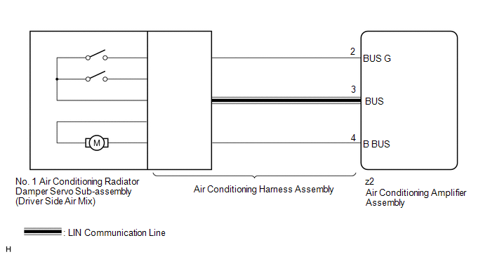
WIRING DIAGRAM
CAUTION / NOTICE / HINT
NOTICE:
- When DTC B1441, B1442, B1443 and B1446 are output at same time, there would be malfunctioning on No. 1 air conditioning radiator damper servo sub-assembly.
-
When the auxiliary battery is disconnected or the air conditioning amplifier assembly is replaced, be sure to perform servo motor initialization.
Click here
.gif)
HINT:
Confirm that no mechanical problem is present because this diagnostic code can be output when either a damper link or the damper is mechanically locked.
PROCEDURE
| 1. | CHECK FOR DTC |
(a) Clear the DTC.
Click here
(b) Check for DTC.
Click here
| Result | Proceed to |
|---|---|
| DTC B1446 is not output | A |
| DTC B1446 is output | B |
| DTC B1446 and B1497 are output | C |
| A | .gif) | USE SIMULATION METHOD TO CHECK |
| C | | GO TO DTC B1497 |
|
.gif)
| 2. | READ VALUE USING TECHSTREAM |
(a) Connect the Techstream to the DLC3.
(b) Turn the power switch on (IG).
(c) Turn the Techstream on.
(d) Operate the driver side temperature adjustment switch.
(e) Enter the following menus: Body Electrical / Air Conditioner / Data List.
(f) Check the value(s) by referring to the table below.
Body Electrical > Air Conditioner > Data List| Tester Display | Measurement Item | Range | Normal Condition | Diagnostic Note |
|---|---|---|---|---|
| Air Mix Servo Targ Pulse(D) | No. 1 air conditioning radiator damper servo sub-assembly (driver side air mix) target pulse | Min.: 128 Max.: 383 | MAX. COLD: 257 (pulse) MAX. HOT: 165 (pulse) | - |
| Air Mix Servo Actual Pulse(D) | No. 1 air conditioning radiator damper servo sub-assembly (driver side air mix) actual pulse | Min.: 128 Max.: 383 | MAX. COLD: 257 (pulse) MAX. HOT: 165 (pulse) | - |
| Tester Display |
|---|
| Air Mix Servo Targ Pulse(D) |
| Air Mix Servo Actual Pulse(D) |
OK:
When the driver side temperature adjustment switch is turned from MAX COLD to MAX HOT, the actual pulse changes following the target pulse.
| Result | Proceed to |
|---|---|
| Target pulse and actual pulse do not change | A |
| Target pulse changes but actual pulse does not change | B |
| Actual pulse changes following the target pulse (When troubleshooting according to the DTC) | C |
| Actual pulse changes following the target pulse (When troubleshooting according to Problem Symptoms Table) | D |
| A | | REPLACE AIR CONDITIONING AMPLIFIER ASSEMBLY |
| C | | GO TO STEP 5 |
| D | | PROCEED TO NEXT SUSPECTED AREA SHOWN IN PROBLEM SYMPTOMS TABLE |
|
| 3. | CHECK NO. 1 AIR CONDITIONING RADIATOR DAMPER SERVO SUB-ASSEMBLY (DRIVER SIDE AIR MIX) |
(a) Replace the No. 1 air conditioning radiator damper servo sub-assembly (driver side air mix).
Click here
HINT:
Since the servo motor cannot be inspected while it is removed from the vehicle, replace the servo motor with a new or known good one and check that the condition returns to normal.
(b) Clear the DTC.
Click here
(c) Check for DTC.
Click here
| Result | Proceed to |
|---|---|
| DTC B1446 is not output | A |
| DTC B1446 is output | B |
| A | | END (NO. 1 AIR CONDITIONING RADIATOR DAMPER SERVO SUB-ASSEMBLY IS DEFECTIVE) |
|
| 4. | CHECK AIR CONDITIONING HARNESS ASSEMBLY |
(a) Replace the air conditioning harness assembly.
Click here
HINT:
Since the air conditioning harness assembly cannot be inspected while it is removed from the vehicle, replace the air conditioning harness assembly with a new or known good one and check that the condition returns to normal.
(b) Clear the DTC.
Click here
(c) Check for DTC.
Click here
| Result | Proceed to |
|---|---|
| DTC B1446 is not output | A |
| DTC B1446 is output | B |
| A | | END (AIR CONDITIONING HARNESS ASSEMBLY IS DEFECTIVE) |
| B | | REPLACE AIR CONDITIONING AMPLIFIER ASSEMBLY |
| 5. | CHECK FOR DTC |
(a) Clear the DTC.
Click here
(b) Check for DTC.
Click here
| Result | Proceed to |
|---|---|
| DTC B1446 is not output | A |
| DTC B1446 is output | B |
| A | | USE SIMULATION METHOD TO CHECK |
| B | | REPLACE AIR CONDITIONING AMPLIFIER ASSEMBLY |
READ NEXT:
 Air Outlet Damper Control Servo Motor Circuit (Rear) (B1449)
DESCRIPTION The No. 2 air conditioning radiator damper servo sub-assembly sends pulse signals to inform the air conditioning amplifier assembly of the damper position. The air conditioning amplifier a
A/C Inverter High Voltage Power Resource System Malfunction (B1471)
DESCRIPTION The hybrid vehicle control ECU monitors the voltage of the HV battery. The hybrid vehicle control ECU stops compressor control and stores this DTC when the monitored voltage is outside the
A/C Inverter High Voltage Output System Malfunction (B1472)
DESCRIPTION The inverter in the compressor with motor assembly outputs high-voltage to operate the motor. If there is an open or short in the output circuit, the hybrid vehicle control ECU will stop c
SEE MORE:
System Description
SYSTEM DESCRIPTION REAR POWER SEAT CONTROL SYSTEM DESCRIPTION
This system has the following functions: reclining, folding and return, and jam protection.
Both the left and right seats are equipped with this system. Each system operates independently.
FUNCTIONS OF MAIN COMPONENTS Component
How To Proceed With Troubleshooting
CAUTION / NOTICE / HINT HINT:
Use the following procedure to troubleshoot the automatic high beam system.
*: Use the Techstream.
PROCEDURE 1. VEHICLE BROUGHT TO WORKSHOP
NEXT 2. INSPECT AUXILIARY BATTERY VOLTAGE (a) Measure the auxiliary battery voltage wit
