- VH-Voltage after Boosting
- Ready Signal
- Emergency Shutdown
Lexus NX: All HV Gate Blocking Range/Performance (P321E-318)
Lexus NX Service Manual / Engine & Hybrid System / 2ar-fxe (hybrid / Battery Control) / Hybrid Control System / All HV Gate Blocking Range/Performance (P321E-318)
DESCRIPTION
The hybrid vehicle control ECU sends a block signal to the motor generator control ECU (MG ECU) to shutdown the power supply to the motor. When the system is not in the on (READY) state, it sends an HSDN (MG shutdown signal) signal from the hybrid vehicle control ECU to the motor generator control ECU (MG ECU) to check the function of the HV gate block. When a malfunction is detected in the HV gate block function, DTCs are stored.
| DTC No. | Detection Item | DTC Detection Condition | Trouble Area | MIL | Warning Indicate |
|---|---|---|---|---|---|
| P321E-318 | All HV Gate Blocking Range/Performance | An open or ground short in the HV gate block signal circuit when the gate is operating. When the HV gate block function check is performed (when the power switch is turned from on (READY) to off), the inverter voltage (VH) drops and current flows in the inverter. (The generator (MG1), motor (MG2) and rear motor (MGR) are malfunctioning.) (1 trip detection logic) |
| Does not come on | Master Warning Light: Comes on |
| DTC No. | Data List |
|---|---|
| P321E-318 | |
WIRING DIAGRAM
Refer to the wiring diagram for the shut down signal circuit.
Click here .gif)
CAUTION / NOTICE / HINT
CAUTION:
- Before inspecting the high-voltage system or disconnecting the low voltage connector of the inverter with converter assembly, take safety precautions such as wearing insulated gloves and removing the service plug grip to prevent electrical shocks. After removing the service plug grip, put it in your pocket to prevent other technicians from accidentally reconnecting it while you are working on the high-voltage system.
-
After removing the service plug grip, wait for at least 10 minutes before touching any of the high-voltage connectors or terminals. After waiting for 10 minutes, check the voltage at the terminals in the inspection point in the inverter with converter assembly. The voltage should be 0 V before beginning work.
Click here
HINT:
Waiting for at least 10 minutes is required to discharge the high-voltage capacitor inside the inverter with converter assembly.
NOTICE:
After turning the power switch off, waiting time may be required before disconnecting the cable from the negative (-) auxiliary battery terminal. Therefore, make sure to read the disconnecting the cable from the negative (-) auxiliary battery terminal notices before proceeding with work.
Click here
HINT:
After the repair, clear the DTCs and perform the following procedure to check that DTCs are not output.
- Wait for 30 seconds or more with the vehicle stopped, the power switch on (READY) and the shift lever in P. Then turn the power switch off and wait for 60 seconds or more.
PROCEDURE
| 1. | CHECK CONNECTOR CONNECTION CONDITION (HYBRID VEHICLE CONTROL ECU CONNECTOR) |
Click here
| NG | .gif) | CONNECT SECURELY |
|
.gif)
| 2. | CHECK CONNECTOR CONNECTION CONDITION (INVERTER WITH CONVERTER ASSEMBLY CONNECTOR) |
Click here
| Result | Proceed to |
|---|---|
| OK | A |
| NG (The connector is not connected securely.) | B |
| NG (The terminals are not making secure contact or are deformed, or water or foreign matter exists in the connector.) | C |
| B | | CONNECT SECURELY |
| C | | REPAIR OR REPLACE HARNESS OR CONNECTOR |
|
| 3. | CHECK HARNESS AND CONNECTOR (HYBRID VEHICLE CONTROL ECU - INVERTER WITH CONVERTER ASSEMBLY) |
CAUTION:
Be sure to wear insulated gloves.
(a) Check that the service plug grip is not installed.
NOTICE:
After removing the service plug grip, do not turn the power switch on (READY), unless instructed by the repair manual because this may cause a malfunction.
(b) Disconnect the A61 hybrid vehicle control ECU connector.
(c) Disconnect the A58 inverter with converter assembly connector.
(d) Measure the resistance according to the value(s) in the table below.
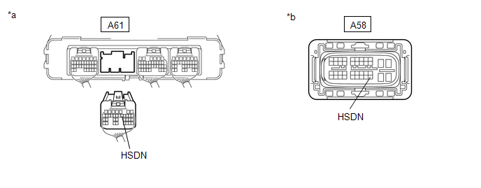
| *a | Rear view of wire harness connector (to Hybrid Vehicle Control ECU) | *b | Front view of wire harness connector (to Inverter with Converter Assembly) |
Standard Resistance:
| Tester Connection | Condition | Specified Condition |
|---|---|---|
| A61-12 (HSDN) or A58-40 (HSDN) - Body ground and other terminals | Power switch off | 10 kΩ or higher |
| A61-12 (HSDN) - A58-40 (HSDN) | Power switch off | Below 1 Ω |
(e) Reconnect the A58 inverter with converter assembly connector.
(f) Reconnect the A61 hybrid vehicle control ECU connector.
| NG | | REPAIR OR REPLACE HARNESS OR CONNECTOR |
|
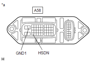
| 4. | CHECK INVERTER WITH CONVERTER ASSEMBLY |
CAUTION:
Be sure to wear insulated gloves.
(a) Check that the service plug grip is not installed.
NOTICE:
After removing the service plug grip, do not turn the power switch on (READY), unless instructed by the repair manual because this may cause a malfunction.
(b) Disconnect the A58 inverter with converter assembly connector.
| (c) Measure the resistance according to the value(s) in the table below. Standard Resistance:
|
|
(d) Reconnect the A58 inverter with converter assembly connector.
| OK | | REPLACE HYBRID VEHICLE CONTROL ECU |
| NG | | REPLACE INVERTER WITH CONVERTER ASSEMBLY |
READ NEXT:
 Part of HV Gate Blocking Range/Performance (P321F-319)
DESCRIPTION Refer to the description for DTC P321E-318. Click here DTC No. Detection Item DTC Detection Condition Trouble Area MIL Warning Indicate P321F-319 Part of HV Gate Block
MG-ECU Power Relay Intermittent Circuit (P324E-788)
DESCRIPTION If the MG ECU, which is built into in the inverter with converter assembly, is reset due to a problem with the power source in the inverter, the hybrid vehicle control ECU will stored this
Lost Communication with ECM / PCM "A" (U0100-530,U0126-735,U0129-527,U0129-528,U0140-146,U0151-763,U0164-827,U1107-436)
DESCRIPTION The hybrid vehicle control ECU transmits and receives signals via CAN communication to and from the ECM, skid control ECU assembly, power steering ECU assembly, main body ECU, airbag ECU a
SEE MORE:
Removal
REMOVAL PROCEDURE 1. REMOVE REAR CONSOLE END PANEL SUB-ASSEMBLY (w/ Wireless Charger) Click here 2. REMOVE CONSOLE BOX ILLUMINATION LIGHT ASSEMBLY (w/ Wireless Charger) (a) Disconnect the connector. *1 Protective Tape (b) Using a screwdriver, detach the 2 claws and remo
Parts Location
PARTS LOCATION ILLUSTRATION *A w/ Panoramic View Monitor System - - *1 FRONT CORNER ULTRASONIC SENSOR (FR SENSOR) *2 FRONT CENTER ULTRASONIC SENSOR (FRC SENSOR) *3 FRONT CENTER ULTRASONIC SENSOR (FLC SENSOR) *4 FRONT CORNER ULTRASONIC SENSOR (FL SENSOR) *5 REAR CO
© 2016-2026 Copyright www.lexunx.com
