Lexus NX: Ambient Temperature Sensor
Components
COMPONENTS
ILLUSTRATION
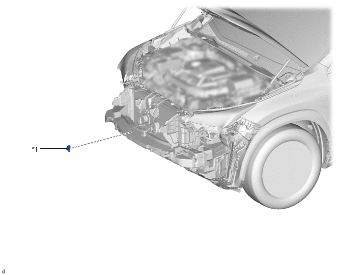
| *1 | THERMISTOR ASSEMBLY (AMBIENT TEMPERATURE SENSOR) | - | - |
Removal
REMOVAL
PROCEDURE
1. REMOVE FRONT BUMPER ASSEMBLY
(a) for Sport Package:
Click here .gif)
(b) except Sport Package:
Click here
2. REMOVE THERMISTOR ASSEMBLY (AMBIENT TEMPERATURE SENSOR)
| (a) Detach the clamp. |
|
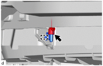
(b) Disconnect the connector and remove the thermistor assembly (ambient temperature sensor).
Inspection
INSPECTION
PROCEDURE
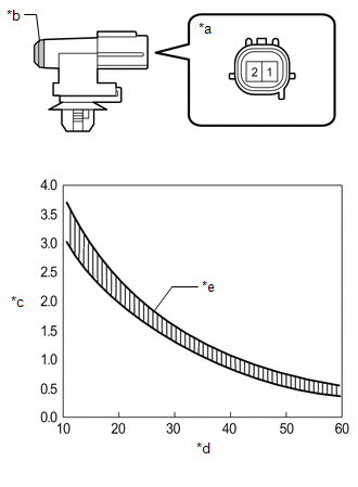
1. INSPECT THERMISTOR ASSEMBLY (AMBIENT TEMPERATURE SENSOR)
| (a) Measure the resistance according to the value(s) in the table below. Standard Resistance:
NOTICE:
HINT: As the temperature increases, the resistance decreases (see the graph).
|
|
Installation
INSTALLATION
PROCEDURE
1. INSTALL THERMISTOR ASSEMBLY (AMBIENT TEMPERATURE SENSOR)
(a) Connect the connector.
(b) Attach the clamp to install the thermistor assembly (ambient temperature sensor).
2. INSTALL FRONT BUMPER ASSEMBLY
(a) for Sport Package:
Click here .gif)
(b) except Sport Package:
Click here
READ NEXT:
 Components
COMPONENTS ILLUSTRATION *1 BLOWER ASSEMBLY - - ILLUSTRATION *1 AIR FILTER CASE *2 AIR REFINER ELEMENT *3 BLOWER WITH FAN MOTOR SUB-ASSEMBLY *4 NO. 1 BLOWER DAMPER SERV
Removal
REMOVAL PROCEDURE 1. REMOVE AIR CONDITIONING UNIT ASSEMBLY Click here 2. REMOVE BLOWER ASSEMBLY (a) Disconnect the No. 1 blower damper servo sub-assembly connector. (b) Detach the 3
SEE MORE:
Do-it-yourself service precautions
If you perform maintenance by
yourself, be sure to follow the correct
procedure as given in these
sections.
Maintenance
Items
Parts and tools
12-volt battery
condition
Grease
Conventional wrench
(for terminal clamp
bolts)
Brake flui
Turn Signal Switch Circuit
DESCRIPTION The combination meter receives the turn signal switch information and controls the turn signal lights. WIRING DIAGRAM CAUTION / NOTICE / HINT NOTICE: When replacing the combination meter assembly, make sure to replace it with a new one. PROCEDURE 1. READ VALUE USING TECHSTREAM (TU
