- State of Charge (All Bat)
- Charge Control Value
- Power Resource IB
- Battery too High Time
Lexus NX: Hybrid Battery Pack State of Charge High (P0C30-390)
Lexus NX Service Manual / Engine & Hybrid System / 2ar-fxe (hybrid / Battery Control) / Hybrid Control System / Hybrid Battery Pack State of Charge High (P0C30-390)
DESCRIPTION
The hybrid vehicle control ECU monitors its internal operation and will store a DTC and perform fail-safe control if it detects the following malfunction.
| DTC No. | Detection Item | DTC Detection Condition | Trouble Area | MIL | Warning Indicate |
|---|---|---|---|---|---|
| P0C30-390 | Hybrid Battery Pack State of Charge High | Charge control malfunction: Charging of the HV battery continues even after charging is prohibited when the hybrid system is malfunctioning and "State of Charge (All Bat)" has reached the upper limit. (1 trip detection logic) |
| Does not come on | Master Warning Light: Comes on |
| DTC No. | Data List |
|---|---|
| P0C30-390 | |
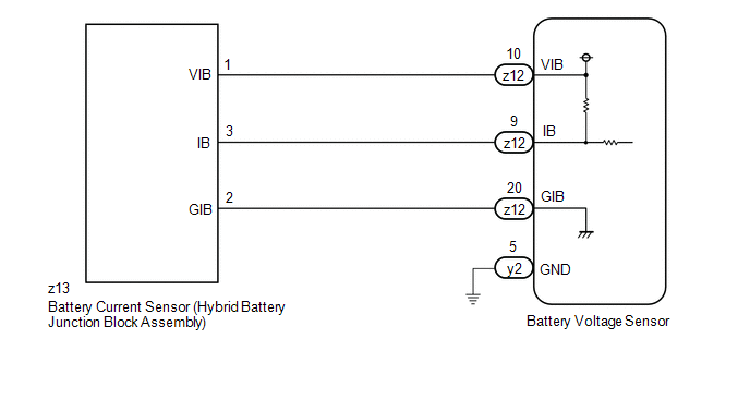
WIRING DIAGRAM
CAUTION / NOTICE / HINT
HINT:
After the repair, clear the DTCs and perform the following procedure to check that DTCs are not output.
-
When the vehicle is stopped with the power switch on (READY) and the shift lever in D, depress the accelerator pedal. The engine speed will increase as well as "State of Charge (All Bat)".
If charge current drops, release the accelerator pedal and then depress it again to maintain charging.
- Check that charging stops when "State of Charge (All Bat)" reaches the upper limit.
PROCEDURE
| 1. | CHECK DTC OUTPUT (HYBRID CONTROL) |
(a) Connect the Techstream to the DLC3.
(b) Turn the power switch on (IG).
(c) Enter the following menus: Powertrain / Hybrid Control / Trouble Codes.
(d) Check for DTCs.
Powertrain > Hybrid Control > Trouble Codes(e) Turn the power switch off.
| DTCs except P0C30-390 are output. | .gif) | GO TO DTC CHART (HYBRID CONTROL SYSTEM) |
|
.gif)
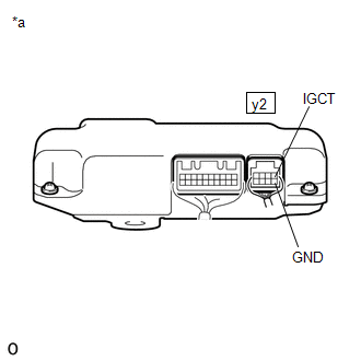
| 2. | CHECK HARNESS AND CONNECTOR (IGCT VOLTAGE) |
CAUTION:
Be sure to wear insulated gloves.
(a) Check that the service plug grip is not installed.
NOTICE:
After removing the service plug grip, do not turn the power switch on (READY), unless instructed by the repair manual because this may cause a malfunction.
(b) Remove the No. 2 hybrid vehicle battery shield reinforcement.
Click here .gif)
(c) Connect the cable to the negative (-) auxiliary battery terminal.
(d) Turn the power switch on (IG).
| (e) Measure the voltage according to the value(s) in the table below. Standard Voltage:
NOTICE: Turning the power switch on (IG) with the service plug grip removed causes other DTCs to be stored. Clear the DTCs after performing this inspection. HINT: As there might be an intermittent malfunction in the battery voltage sensor power source circuit, inspect the following even if the measured voltage is as specified:
|
|
(f) Turn the power switch off.
(g) Disconnect the cable from the negative (-) auxiliary battery terminal.
(h) Install the No. 2 hybrid vehicle battery shield reinforcement.
| NG | | REPAIR OR REPLACE HARNESS OR CONNECTOR (BATTERY VOLTAGE SENSOR POWER SOURCE CIRCUIT) |
|
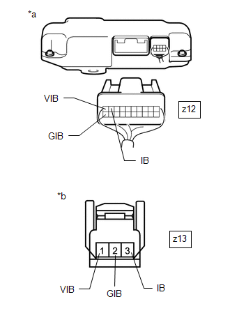
| 3. | CHECK HARNESS AND CONNECTOR (BATTERY VOLTAGE SENSOR - HYBRID BATTERY JUNCTION BLOCK ASSEMBLY) |
CAUTION:
Be sure to wear insulated gloves.
(a) Check that the service plug grip is not installed.
NOTICE:
After removing the service plug grip, do not turn the power switch on (READY), unless instructed by the repair manual because this may cause a malfunction.
(b) Remove the No. 2 hybrid vehicle battery shield reinforcement.
Click here
(c) Disconnect the HV battery high voltage connector from the hybrid battery junction block assembly.
NOTICE:
Before disconnecting the connector, check that it is not loose or disconnected.
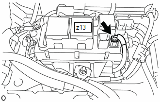
| (d) Disconnect the z13 battery current sensor connector from the hybrid battery junction block assembly. NOTICE: Before disconnecting the connector, check that it is not loose or disconnected. |
|
(e) Disconnect the battery voltage sensor connector.
NOTICE:
Before disconnecting the connector, check that it is not loose or disconnected.
| (f) Measure the resistance according to the value(s) in the tables below. Standard Resistance (Check for Open):
Standard Resistance (Check for Short):
NOTICE: When taking a measurement with a tester, do not apply excessive force to the tester probe to avoid damaging the holder. HINT: As the battery harness is not available as a supply part, if the harness cannot be repaired, replace the HV battery. |
|
(g) Reconnect the battery voltage sensor connector.
(h) Reconnect the battery current sensor connector to the hybrid battery junction block assembly.
(i) Reconnect the HV battery high voltage connector to the hybrid battery junction block assembly.
(j) Install the No. 2 hybrid vehicle battery shield reinforcement.
| NG | | REPAIR HARNESS OR CONNECTOR (BATTERY CURRENT SENSOR) |
|
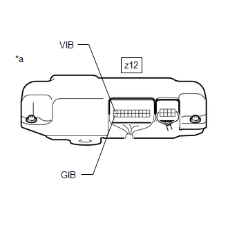
| 4. | CHECK BATTERY VOLTAGE SENSOR (VIB VOLTAGE) |
CAUTION:
Be sure to wear insulated gloves.
(a) Check that the service plug grip is not installed.
NOTICE:
After removing the service plug grip, do not turn the power switch on (READY), unless instructed by the repair manual because this may cause a malfunction.
(b) Remove the No. 2 hybrid vehicle battery shield reinforcement.
Click here
(c) Connect the cable to the negative (-) auxiliary battery terminal.
(d) Turn the power switch on (IG).
| (e) Measure the voltage according to the value(s) in the table below. Standard Voltage:
NOTICE: Turning the power switch on (IG) with the service plug grip removed causes other DTCs to be stored. Clear the DTCs after performing this inspection. |
|
(f) Turn the power switch off.
(g) Disconnect the cable from the negative (-) auxiliary battery terminal.
(h) Install the No. 2 hybrid vehicle battery shield reinforcement.
| NG | | GO TO STEP 7 |
|
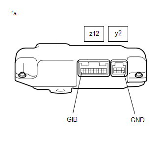
| 5. | CHECK BATTERY VOLTAGE SENSOR (GIB TERMINAL - GND TERMINAL) |
CAUTION:
Be sure to wear insulated gloves and protective goggles.
(a) Check that the service plug grip is not installed.
NOTICE:
After removing the service plug grip, do not turn the power switch on (READY), unless instructed by the repair manual because this may cause a malfunction.
(b) Remove the No. 2 hybrid vehicle battery shield reinforcement.
Click here
(c) Disconnect the z12 and y2 battery voltage sensor connectors.
NOTICE:
Before disconnecting the connector, check that it is not loose or disconnected.
| (d) Measure the resistance according to the value(s) in the tables below. Standard Resistance:
|
|
(e) Reconnect the z12 and y2 battery voltage sensor connectors.
(f) Install the No. 2 hybrid vehicle battery shield reinforcement.
| NG | | REPLACE HYBRID BATTERY JUNCTION BLOCK ASSEMBLY |
|
| 6. | CHECK HYBRID VEHICLE CONTROL ECU (POWER RESOURCE IB, BATT PACK CURRENT VAL) |
(a) Connect the Techstream to the DLC3.
(b) Turn the power switch on (IG).
NOTICE:
During the inspection, make sure to only turn the power switch on (IG). Do not turn the power switch on (READY).
(c) Enter the following menus: Powertrain / Hybrid Control / Data List / Power Resource IB, Batt Pack Current Val.
Powertrain > Hybrid Control > Data List| Tester Display |
|---|
| Power Resource IB |
| Batt Pack Current Val |
(d) With the power switch on (IG), monitor Data List item "Power Resource IB" and "Batt Pack Current" for 1 minute.
| Result | Proceed to |
|---|---|
| The value of Data List item "Power Resource IB" and "Batt Pack Current" is -0.5 A or less or 0.5 A or more. | A |
| Other than above | B |
(e) Turn the power switch off.
| A | | REPLACE BATTERY VOLTAGE SENSOR |
| B | | REPLACE HYBRID VEHICLE CONTROL ECU |
| 7. | CHECK BATTERY VOLTAGE SENSOR (VIB VOLTAGE) |
CAUTION:
Be sure to wear insulated gloves.
(a) Check that the service plug grip is not installed.
NOTICE:
After removing the service plug grip, do not turn the power switch on (READY), unless instructed by the repair manual because this may cause a malfunction.
(b) Remove the No. 2 hybrid vehicle battery shield reinforcement.
Click here
(c) Disconnect the HV battery high voltage connector from the hybrid battery junction block assembly.
NOTICE:
Before disconnecting the connector, check that it is not loose or disconnected.
| (d) Disconnect the z13 battery current sensor connector from the hybrid battery junction block assembly. NOTICE: Before disconnecting the connector, check that it is not loose or disconnected. |
|
(e) Connect the cable to the negative (-) auxiliary battery terminal.
(f) Turn the power switch on (IG).
| (g) Measure the voltage according to the value(s) in the table below. Standard Voltage:
NOTICE: Turning the power switch on (IG) with the service plug grip removed causes other DTCs to be stored. Clear the DTCs after performing this inspection. |
|
(h) Turn the power switch off.
(i) Disconnect the cable from the negative (-) auxiliary battery terminal.
(j) Reconnect the battery current sensor connector to the hybrid battery junction block assembly.
(k) Reconnect the HV battery high voltage connector to the hybrid battery junction block assembly.
(l) Install the No. 2 hybrid vehicle battery shield reinforcement.
| OK | | REPLACE HYBRID BATTERY JUNCTION BLOCK ASSEMBLY |
| NG | | REPLACE BATTERY VOLTAGE SENSOR |
READ NEXT:
 DC / DC Converter Temperature Sensor "A" Range / Performance (P0C39-626,P0C3C-625)
DTC SUMMARY MALFUNCTION DESCRIPTION These DTCs indicate the boost converter temperature sensor (upper) value is abnormal. The cause of this malfunction may be one of the following: Internal inverter
DC / DC Converter Temperature Sensor "B" Range / Performance (P0C3E-628,P0C41-627)
DTC SUMMARY MALFUNCTION DESCRIPTION These DTCs indicate the boost converter temperature sensor (lower) value is abnormal. The cause of this malfunction may be one of the following: Internal inverter
Motor Electronics Coolant Pump "A" Control Performance (P0C73-776)
DESCRIPTION The inverter water pump assembly transmits rotation speed information to the hybrid vehicle control ECU. The hybrid vehicle control ECU monitors the speed and detects malfunctions. DTC
SEE MORE:
Certification Ecu
ComponentsCOMPONENTS ILLUSTRATION *1 CERTIFICATION ECU (SMART KEY ECU ASSEMBLY) *2 ECU INTEGRATION BOX RH *3 GLOVE COMPARTMENT DOOR ASSEMBLY *4 NO. 2 INSTRUMENT PANEL UNDER COVER SUB-ASSEMBLY N*m (kgf*cm, ft.*lbf): Specified torque - - RemovalREMOVAL PROCEDURE 1.
Low Output Signal of Rear Speed Sensor RH (C1273,C1274,C1466,C1467)
DESCRIPTION Each speed sensor detects the wheel speed and sends the signals to the skid control ECU (brake booster with master cylinder assembly). These signals are used for ABS control. DTCs C1273 and C1274 are cleared when the speed sensor sends a wheel speed signal or when Test Mode ends. DTCs C1
© 2016-2026 Copyright www.lexunx.com
