
Lexus NX: Components
Lexus NX Service Manual / Engine & Hybrid System / 2ar-fxe (engine Mechanical) / Cylinder Block / Components
COMPONENTS
ILLUSTRATION
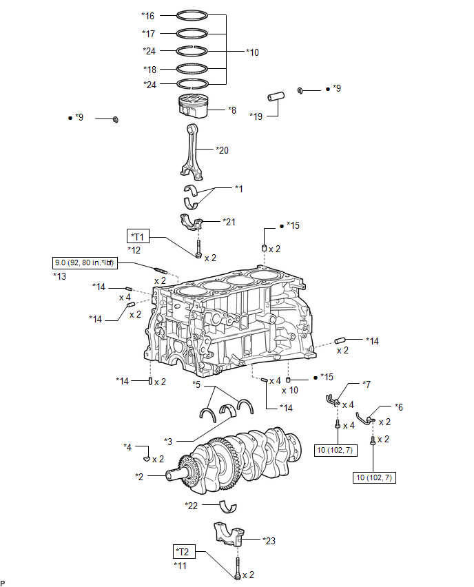
| *1 | CONNECTING ROD BEARING | *2 | CRANKSHAFT |
| *3 | CRANKSHAFT BEARING | *4 | CRANKSHAFT PULLEY SET KEY |
| *5 | CRANKSHAFT THRUST WASHER | *6 | NO. 1 OIL NOZZLE SUB-ASSEMBLY |
| *7 | NO. 2 OIL NOZZLE SUB-ASSEMBLY | *8 | PISTON |
| *9 | PISTON PIN HOLE SNAP RING | *10 | PISTON RING SET |
| *11 | CRANKSHAFT BEARING CAP SET BOLT | *12 | CONNECTING ROD BOLT |
| *13 | STUD BOLT | *14 | STRAIGHT PIN |
| *15 | RING PIN | *16 | NO. 1 COMPRESSION RING |
| *17 | NO. 2 COMPRESSION RING | *18 | OIL RING EXPANDER |
| *19 | PISTON PIN | *20 | CONNECTING ROD |
| *21 | CONNECTING ROD CAP | *22 | NO. 2 CRANKSHAFT BEARING |
| *23 | CRANKSHAFT BEARING CAP | *24 | OIL RING SIDE RAIL |
.png) | N*m (kgf*cm, ft.*lbf): Specified torque | ● | Non-reusable part |
| *T1 | 1st: 40 (408, 30) 2nd: Turn 90° | *T2 | 1st: 20 (204, 15) 2nd: 40 (408, 30) 3rd: Turn 90° |
READ NEXT:
 Inspection
INSPECTION PROCEDURE 1. INSPECT CYLINDER BLOCK FOR WARPAGE (a) Using a precision straightedge and feeler gauge, measure the warpage of the surface that contacts the cylinder head gasket. Maximum wa
Replacement
REPLACEMENT PROCEDURE 1. REPLACE RING PIN NOTICE: It is not necessary to remove the ring pin unless it is being replaced. (a) Remove the 12 ring pins. (b) Using a plastic-faced hammer, install 12 new
Reassembly
REASSEMBLY CAUTION / NOTICE / HINT HINT: Perform "Inspection After Repairs" after replacing the piston or piston ring. Click here PROCEDURE 1. INSTALL STUD BOLT NOTICE: If a stud bolt is deformed or
SEE MORE:
Transmitter Battery
ReplacementREPLACEMENT PROCEDURE 1. REMOVE TRANSMITTER BATTERY (a) Push the release hook knob and extract the mechanical key. (b) Using a screwdriver with its tip wrapped in protective tape, remove the transmitter housing cover as shown in the illustration. HINT: Tape the screwdri
Data List / Active Test
DATA LIST / ACTIVE TEST NOTICE: In the table below, the values listed under "Normal Condition" are reference values. Do not depend solely on these reference values when deciding whether a part is faulty or not. HINT: Using the Techstream to read the Data List allows the values or states of switches,
© 2016-2026 Copyright www.lexunx.com
