Lexus NX: Reassembly
REASSEMBLY
CAUTION / NOTICE / HINT
HINT:
Perform "Inspection After Repairs" after replacing the piston or piston ring.
Click here .gif)
PROCEDURE
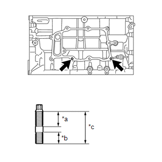
1. INSTALL STUD BOLT
NOTICE:
If a stud bolt is deformed or its threads are damaged, replace it.
| (a) Using an E8 "TORX" socket wrench, install the stud bolts. Torque: 9.0 N·m {92 kgf·cm, 80 in·lbf} |
|
2. INSTALL NO. 2 OIL NOZZLE SUB-ASSEMBLY
(a) Using a 5 mm hexagon wrench, install the 4 No. 2 oil nozzle sub-assemblies with the 4 bolts.
Torque:
10 N·m {102 kgf·cm, 7 ft·lbf}
3. INSTALL NO. 1 OIL NOZZLE SUB-ASSEMBLY
(a) Using a 5 mm hexagon wrench, install the 2 No. 1 oil nozzle sub-assemblies with the 2 bolts.
Torque:
10 N·m {102 kgf·cm, 7 ft·lbf}
4. INSTALL PISTON
HINT:
Perform "Inspection After Repairs" after replacing the piston.
Click here
(a) Using a small screwdriver, install a new piston pin hole snap ring at one end of the piston pin hole.
(b) Gradually heat the piston up to 80 to 90°C (176 to 194°F).
(c) Coat the piston, piston pin and connecting rod with engine oil.
| (d) Align the front marks of the piston and connecting rod, insert the connecting rod into the piston, and then push in the piston pin with your thumb until the pin comes into contact with the piston pin hole snap ring. HINT: The piston and piston pin are a matched set. |
|
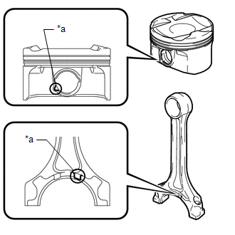
| (e) Using a small screwdriver, install a new piston pin hole snap ring on the other side of the piston pin hole. HINT: Be sure that the end gap of the snap ring is not aligned with the service hole cutout portion of the piston. |
|
(f) Check the fitting condition between the piston and piston pin.
(1) Move the connecting rod back and forth on the piston pin. Check the fitting condition.
If abnormal movement is felt, replace the piston and piston pin as a set.
(2) Rotate the piston back and forth on the piston pin. Check the fitting condition.
If abnormal movement is felt, replace the piston and pin as a set.
5. INSTALL PISTON RING SET
HINT:
Perform "Inspection After Repairs" after replacing the piston ring.
Click here
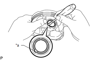
| (a) Install the oil ring expander and 2 oil ring side rails by hand. |
|
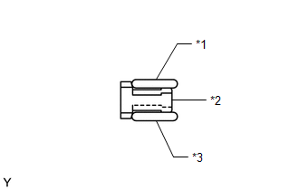
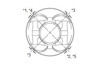
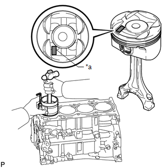
(b) Using a piston ring expander, install the 2 compression rings with the code mark positioned as shown in the illustration.
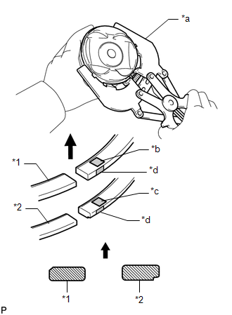
| *1 | No. 1 Compression Ring |
| *2 | No. 2 Compression Ring |
| *a | Piston Ring Expander |
| *b | Code Mark (1NA) |
| *c | Code Mark (2N) |
| *d | Paint Mark |
.png) | Upward |
NOTICE:
Install the compression ring with the code mark facing upward.
6. INSTALL CRANKSHAFT PULLEY SET KEY
(a) Install the 2 crankshaft pulley set keys to the crankshaft.
7. INSTALL CRANKSHAFT BEARING
| (a) Clean the main journal and both surfaces of the bearing. |
|
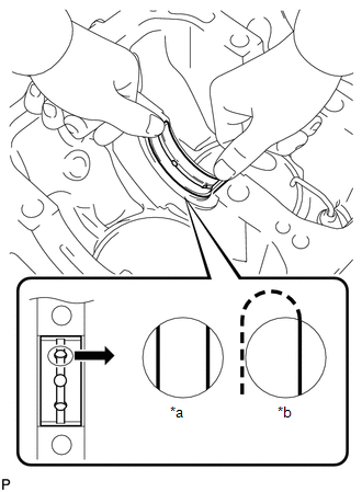
(b) Install the crankshaft bearing to the cylinder block as shown in the illustration.
NOTICE:
- Do not apply engine oil to the crankshaft bearings or their contact surfaces.
- Both sides of the oil groove in the cylinder block should be visible through the oil feed holes in the crankshaft bearing. The amount visible on each side of the holes should be equal.
- Do not allow coolant to come into contact with the bearing inner surface. If any coolant comes into contact with the bearing inner surface, replace the crankshaft bearing with a new one.
HINT:
The colors of the crankshat bearing and No. 2 crankshaft bearing differ depending on the installation position.
| Installation Position | Crankshaft Bearing | No. 2 Crankshaft Bearing |
| No. 1 | Black | Black |
| No. 2 | Silver | Silver |
| No. 3 | Black | Silver |
| No. 4 | Silver | Silver |
| No. 5 | Silver | Black |
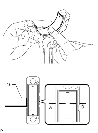
| (c) Install the No. 2 crankshaft bearing to the crankshaft bearing cap. |
|
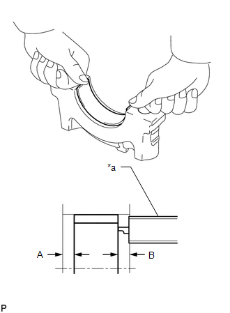
(d) Using a vernier caliper, measure the distance between the edges of the crankshaft bearing cap and No. 2 crankshaft bearing.
Dimension A - B or B - A:
0 to 0.7 mm (0 to 0.0276 in.)
NOTICE:
- Do not apply engine oil to the No. 2 crankshaft bearings and the contact surfaces.
- Do not allow coolant to come into contact with the bearing inner surface. If any coolant comes into contact with the bearing inner surface, replace the No. 2 crankshaft bearing with a new one.
8. INSTALL CRANKSHAFT THRUST WASHER
| (a) Apply engine oil to the thrust washers. |
|
(b) Install the 2 thrust washers to the No. 3 journal position of the cylinder block with the oil grooves facing outward.
9. INSTALL CRANKSHAFT
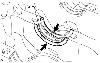
| (a) Apply engine oil to the crankshaft bearing, and then install the crankshaft to the cylinder block. |
|
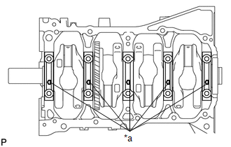
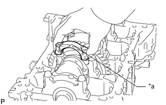
(b) Examine the front marks and numbers, and then install the crankshaft bearing caps to the cylinder block with the front marks as shown in the illustration.
(c) Apply a light coat of engine oil to the threads and under the heads of the crankshaft bearing cap set bolts.
(d) Tighten the crankshaft bearing cap set bolts.
HINT:
The crankshaft bearing cap set bolts are tightened in 3 progressive steps.
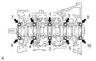
| (1) Step 1: Using several steps, install and uniformly tighten the 10 crankshaft bearing cap set bolts in the sequence shown in the illustration. Torque: 20 N·m {204 kgf·cm, 15 ft·lbf} |
|
(2) Step 2:
Tighten the 10 crankshaft bearing cap set bolts again in the sequence shown in the illustration.
Torque:
40 N·m {408 kgf·cm, 30 ft·lbf}
If a crankshaft bearing cap set bolt does not meet the specified torque, replace it.
(3) Mark the front side of each crankshaft bearing cap set bolt with paint.
(4) Step 3:
Tighten the 10 crankshaft bearing cap set bolts 90° in the order shown in step 1.
(5) Check that the paint marks are now at a 90° angle to the front.
(e) Check that the crankshaft turns smoothly.
10. INSTALL CONNECTING ROD BEARING
| (a) Clean the bearing contact surface of the connecting rod and connecting rod cap, and both surfaces of both connecting rod bearings. |
|
(b) Install the connecting rod bearings to the connecting rods and connecting rod caps.
(c) Using a vernier caliper, measure the distance between the edges of the connecting rod and connecting rod bearing, and the edges of the connecting rod cap and connecting rod bearing.
Dimension A - B or B - A:
0 to 0.7 mm (0 to 0.0276 in.)
NOTICE:
- Do not apply engine oil to the bearings or the contact surfaces.
- Do not allow coolant to come into contact with the bearing inner surface. If any coolant comes into contact with the bearing inner surface, replace the bearing with a new one.
11. INSTALL PISTON WITH CONNECTING ROD
(a) Apply engine oil to the cylinder walls, pistons, and surfaces of the connecting rod bearings.
| (b) Position the piston rings so that the ring ends are as shown in the illustration. HINT: The oil ring expander can be installed with the ring ends in either of the directions shown in the illustration. |
|
| (c) Using a hammer handle and piston ring compressor, press a piston with connecting rod into each cylinder with the front mark of the piston facing forward. NOTICE: When inserting the piston with connecting rod into the cylinder block, make sure the oil nozzle does not interfere with the connecting rod. HINT: The front mark is "2H" printed in raised letters. |
|
| (d) Check that the front mark of the connecting rod cap is facing in the correct direction. NOTICE: Match the numbered connecting rod cap with the correct connecting rod. |
|
(e) Apply a light coat of engine oil to the threads and under the heads of the connecting rod bolts.
(f) Install the connecting rod bolts.
HINT:
The connecting rod bolts are tightened in 2 progressive steps.
(1) Step 1:
Install and alternately tighten the connecting rod bolts of each connecting rod cap in several steps.
Torque:
40 N·m {408 kgf·cm, 30 ft·lbf}
(2) Mark the front side of each connecting rod cap bolt with paint.
(3) Step 2:
Tighten the cap bolts 90°.
(4) Check that the paint marks are now at a 90° angle to the front.
(g) Check that the crankshaft turns smoothly.
READ NEXT:
 Precaution
PRECAUTION HINT:
Any digits beyond the 0.01 mm (1/1000 in.) place for standard, minimum and maximum values should be used as a reference only.
When both standard and maximum or minimum values are
Components
COMPONENTS ILLUSTRATION *1 EXHAUST VALVE *2 EXHAUST VALVE GUIDE BUSH *3 INTAKE VALVE *4 INTAKE VALVE GUIDE BUSH *5 NO. 1 STRAIGHT SCREW PLUG *6 NO. 2 STRAIGHT SCREW PLUG
SEE MORE:
Open in One Side of Bus 2 Branch Line
DESCRIPTION When the CAN bus main lines are normal (no open, short to ground, short to +B or short between lines) and there is an ECU or sensor on the "Communication Bus Check" screen that is indicated as not communicating or whose connection status on the "Communication Bus Check" screen changes in
Climate Control System does not Operate on Passenger Side
DESCRIPTION The air conditioning control assembly sends operation signals to the air conditioning amplifier assembly via the LIN communication line. The air conditioning amplifier assembly actives the seat blowers according to these signals. WIRING DIAGRAM CAUTION / NOTICE / HINT NOTICE:
The cli
