Lexus NX: Components
Lexus NX Service Manual / Engine & Hybrid System / 2ar-fxe (engine Mechanical) / Cylinder Head / Components
COMPONENTS
ILLUSTRATION
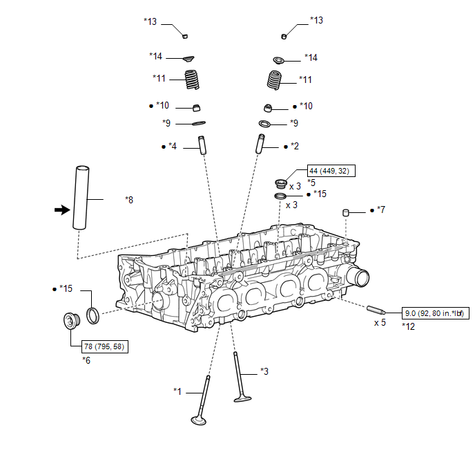
| *1 | EXHAUST VALVE | *2 | EXHAUST VALVE GUIDE BUSH |
| *3 | INTAKE VALVE | *4 | INTAKE VALVE GUIDE BUSH |
| *5 | NO. 1 STRAIGHT SCREW PLUG | *6 | NO. 2 STRAIGHT SCREW PLUG |
| *7 | RING PIN | *8 | SPARK PLUG TUBE |
| *9 | VALVE SPRING SEAT | *10 | VALVE STEM OIL SEAL |
| *11 | INNER COMPRESSION SPRING | *12 | STUD BOLT |
| *13 | VALVE SPRING RETAINER LOCK | *14 | VALVE SPRING RETAINER |
| *15 | GASKET | - | - |
.png) | N*m (kgf*cm, ft.*lbf): Specified torque | ● | Non-reusable part |
.png) | Toyota Genuine Adhesive 1324, Three Bond 1324 or equivalent | ★ | Precoated part |
READ NEXT:
 Disassembly
DISASSEMBLY PROCEDURE 1. REMOVE INTAKE VALVE (a) Using SST and wooden blocks, compress the inner compression spring and remove the valve spring retainer locks. SST: 09202-70020 SST: 09202-00021
Inspection
INSPECTION PROCEDURE 1. INSPECT CYLINDER HEAD SUB-ASSEMBLY (a) Using a precision straightedge and feeler gauge, measure the warpage of the contact surfaces where the cylinder head contacts the cylinde
Replacement
REPLACEMENT PROCEDURE 1. REPLACE INTAKE VALVE GUIDE BUSH (a) Heat the cylinder head sub-assembly to approximately 80 to 100°C (176 to 212°F). (b) Place the cylinder head sub-assembly on wooden block
SEE MORE:
Precaution
PRECAUTION PRECAUTION FOR DISCONNECTING CABLE FROM NEGATIVE AUXILIARY BATTERY TERMINAL NOTICE: When disconnecting the cable from the negative (-) auxiliary battery terminal, perform steering angle sensor zero point calibration after the cable is reconnected. Click here PRECAUTIONS FOR LANE TRACING
Installation
INSTALLATION CAUTION / NOTICE / HINT CAUTION: Wear protective gloves. Sharp areas on the parts may injure your hands. PROCEDURE 1. INSTALL SEPARATE TYPE REAR SEATBACK COVER LH (REAR SEATBACK HEATER ASSEMBLY LH) (for LH Side) HINT:
When installing the seat cover, refer to the precautions in order
© 2016-2026 Copyright www.lexunx.com
