Lexus NX: Inspection
INSPECTION
PROCEDURE
1. INSPECT CYLINDER HEAD SUB-ASSEMBLY
(a) Using a precision straightedge and feeler gauge, measure the warpage of the contact surfaces where the cylinder head contacts the cylinder block and manifold.
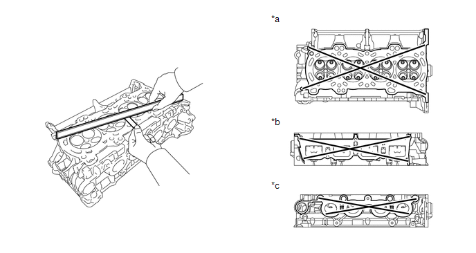
| *a | Cylinder Head Lower Side | *b | Intake Manifold Side |
| *c | Exhaust Manifold Side | - | - |
Maximum Warpage:
| Item | Specified Condition |
|---|---|
| Cylinder head lower side | 0.05 mm (0.00197 in.) |
| Intake manifold side | 0.10 mm (0.00394 in.) |
| Exhaust manifold side | 0.10 mm (0.00394 in.) |
If the warpage is more than the maximum, replace the cylinder head sub-assembly.
(b) Using a dye penetrant, check the intake ports, exhaust ports and cylinder surface for cracks.
If cracked, replace the cylinder head sub-assembly.
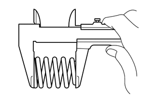
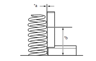
2. INSPECT INNER COMPRESSION SPRING
| (a) Using a vernier caliper, measure the free length of the inner compression spring. Standard free length: 47.2 mm (1.86 in.) |
|
| (b) Using a steel square, measure the deviation of the inner compression spring. Maximum deviation: 1.05 mm (0.0413 in.) Maximum angle: 2° If the deviation is more than the maximum, replace the inner compression spring. |
|
3. INSPECT INTAKE VALVE
(a) Using a micrometer, measure the diameter of the valve stem.
Standard valve stem diameter:
5.470 to 5.485 mm (0.2154 to 0.2159 in.)
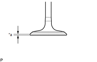
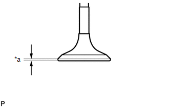
| (b) Using a vernier caliper, measure the valve head margin thickness. Standard margin thickness: 1.0 mm (0.0394 in.) Minimum margin thickness: 0.50 mm (0.0197 in.) If the margin thickness is less than the minimum, replace the intake valve. |
|
(c) Using a vernier caliper, measure the overall length of the valve.
Standard overall length:
103.92 mm (4.09 in.)
Minimum overall length:
103.42 mm (4.07 in.)
If the overall length is less than the minimum, replace the intake valve.
4. INSPECT EXHAUST VALVE
(a) Using a micrometer, measure the diameter of the valve stem.
Standard valve stem diameter:
5.465 to 5.480 mm (0.2152 to 0.2157 in.)
| (b) Using a vernier caliper, measure the valve head margin thickness. Standard margin thickness: 1.0 mm (0.0394 in.) Minimum margin thickness: 0.50 mm (0.0197 in.) If the margin thickness is less than the minimum, replace the exhaust valve. |
|
(c) Using a vernier caliper, measure the overall length of the valve.
Standard overall length:
112.91 mm (4.45 in.)
Minimum overall length:
112.41 mm (4.43 in.)
If the overall length is less than the minimum, replace the exhaust valve.
5. INSPECT VALVE GUIDE BUSH OIL CLEARANCE
| (a) Using a caliper gauge, measure the inside diameter of the valve guide bush. Standard bush inside diameter: 5.510 to 5.530 mm (0.2169 to 0.2177 in.) |
|
(b) Subtract the valve stem diameter measurement from the guide bush inside diameter measurement.
Standard Oil Clearance:
| Item | Specified Condition |
|---|---|
| Intake | 0.025 to 0.060 mm (0.000984 to 0.00236 in.) |
| Exhaust | 0.030 to 0.065 mm (0.00118 to 0.00256 in.) |
Maximum Oil Clearance:
| Item | Specified Condition |
|---|---|
| Intake | 0.08 mm (0.00315 in.) |
| Exhaust | 0.10 mm (0.00394 in.) |
If the oil clearance is more than the maximum, replace the valve and valve guide bush.
6. INSPECT INTAKE VALVE SEAT
(a) Apply a light coat of Prussian blue to the valve face.
| (b) Lightly press the valve face against the intake valve seat. HINT: Do not rotate the valve while pressing the valve. |
|
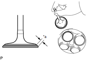
(c) Check the valve face and intake valve seat.
(1) Check that the contact surfaces of the intake valve seat and valve face are in the middle area of their respective surfaces, with the width between 1.0 and 1.4 mm (0.0394 and 0.0551 in.).
If not, correct the intake valve seat.
(2) Check that the contact surfaces of the intake valve seat and valve face are even around the entire intake valve seat.
If not, correct the intake valve seat.
7. INSPECT EXHAUST VALVE SEAT
(a) Apply a light coat of Prussian blue to the valve face.
| (b) Lightly press the valve face against the exhaust valve seat. HINT: Do not rotate the valve while pressing the valve. |
|
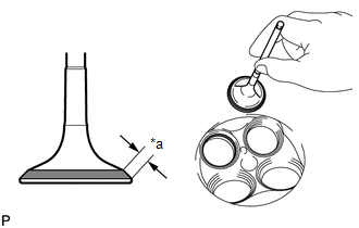
(c) Check the valve face and exhaust valve seat.
(1) Check that the contact surfaces of the exhaust valve seat and valve face are in the middle area of their respective surfaces, with the width between 1.2 and 1.6 mm (0.0472 and 0.0630 in.).
If not, correct the exhaust valve seat.
(2) Check that the contact surfaces of the exhaust valve seat and valve face are even around the entire exhaust valve seat.
If not, correct the exhaust valve seat.
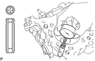
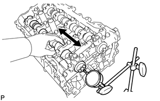
8. INSPECT CAMSHAFT THRUST CLEARANCE
(a) Inspect the camshaft and No. 2 camshaft.
(1) Install the camshaft and No. 2 camshaft.
Click here .gif)
| (2) Using a dial indicator, measure the thrust clearance while moving the camshaft back and forth. Standard thrust clearance: 0.060 to 0.155 mm (0.00236 to 0.00610 in.) Maximum thrust clearance: 0.170 mm (0.00669 in.) If the thrust clearance is more than the maximum, replace the camshaft housing sub-assembly. If the thrust surface is damaged, replace the camshaft. |
|
READ NEXT:
 Replacement
REPLACEMENT PROCEDURE 1. REPLACE INTAKE VALVE GUIDE BUSH (a) Heat the cylinder head sub-assembly to approximately 80 to 100°C (176 to 212°F). (b) Place the cylinder head sub-assembly on wooden block
Reassembly
REASSEMBLY CAUTION / NOTICE / HINT HINT: Perform "Inspection After Repairs" after replacing the cylinder head sub-assembly. Click here PROCEDURE 1. INSTALL CYLINDER HEAD STUD BOLT NOTICE: If a stud
Repair
REPAIR PROCEDURE 1. REPAIR INTAKE VALVE SEAT NOTICE:
Repair the seat while checking the seating position.
Keep the lip free of foreign matter.
Take off the cutter gradually to make the intake v
SEE MORE:
Diagnosis System
DIAGNOSIS SYSTEM FUNCTION OF WARNING INDICATOR AND MESSAGE (a) If the pre-collision system is not functioning properly, the driver is warned by the PCS warning light and a warning message displayed on the multi-information display. Master Warning Indicator Warning Message Detail DTC/RoB P
Inspection
INSPECTION PROCEDURE 1. INSPECT FUEL LID WITH MOTOR LOCK ASSEMBLY (a) Check the operation of the fuel lid with lock motor assembly. (1) Apply auxiliary battery voltage to the fuel lid with motor lock assembly connector, and check that the fuel lid with motor lock assembly operates smoothly as fol
