Lexus NX: Components
COMPONENTS
ILLUSTRATION
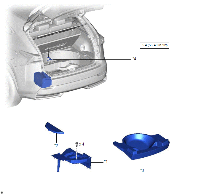
| *1 | DECK FLOOR BOX LH | *2 | NO. 3 DECK BOARD SUB-ASSEMBLY |
| *3 | REAR DECK FLOOR BOX | *4 | AUXILIARY BATTERY NEGATIVE TERMINAL |
 | N*m (kgf*cm, ft.*lbf): Specified torque | - | - |
ILLUSTRATION
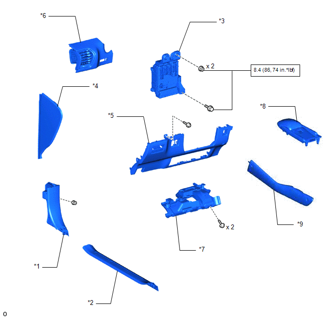
| *1 | COWL SIDE TRIM BOARD LH | *2 | DOOR SCUFF PLATE ASSEMBLY LH |
| *3 | INSTRUMENT PANEL JUNCTION BLOCK ASSEMBLY | *4 | INSTRUMENT SIDE PANEL LH |
| *5 | LOWER NO. 1 INSTRUMENT PANEL FINISH PANEL | *6 | NO. 1 INSTRUMENT PANEL SAFETY PAD SUB-ASSEMBLY |
| *7 | NO. 1 INSTRUMENT PANEL UNDER COVER SUB-ASSEMBLY | *8 | REAR CONSOLE ARMREST ASSEMBLY |
| *9 | UPPER NO. 2 CONSOLE PANEL GARNISH | - | - |
| | N*m (kgf*cm, ft.*lbf): Specified torque | - | - |
ILLUSTRATION
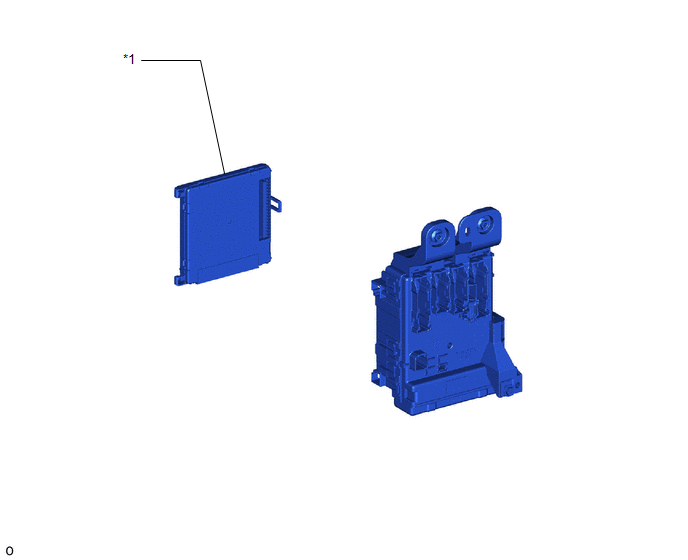
| *1 | MULTIPLEX NETWORK BODY ECU (MAIN BODY ECU) | - | - |
READ NEXT:
 Removal
REMOVAL PROCEDURE 1. REMOVE NO. 3 DECK BOARD SUB-ASSEMBLY Click here 2. REMOVE REAR DECK FLOOR BOX Click here 3. REMOVE DECK FLOOR BOX LH Click here 4. PRECAUTION CAUTION: Be sure to read Precou
Installation
INSTALLATION PROCEDURE 1. INSTALL MULTIPLEX NETWORK BODY ECU (MAIN BODY ECU) NOTICE:
Make sure that no foreign matter gets on the connecting surfaces.
Do not touch the ECU connector.
(a) Inser
SEE MORE:
Precaution
PRECAUTION NOTICE: When disassembling the headlight assembly, use static electricity countermeasures SST (desktop antistatic mat set) and observe all precautions to prevent damage to the system by electrostatic discharge (ESD). STATIC ELECTRICITY COUNTERMEASURES SST SST:Desktop antistatic mat set (0
On-vehicle Inspection
ON-VEHICLE INSPECTION CAUTION / NOTICE / HINT NOTICE:
When the brake pedal is first depressed after replacing the brake pads or pushing back the disc brake piston, DTC C1214 may be output. As there is no malfunction, clear the DTC.
While the auxiliary battery is connected, even if the power swi
© 2016-2026 Copyright www.lexunx.com
