Lexus NX: Removal
REMOVAL
PROCEDURE
1. REMOVE NO. 3 DECK BOARD SUB-ASSEMBLY
Click here .gif)
2. REMOVE REAR DECK FLOOR BOX
Click here
3. REMOVE DECK FLOOR BOX LH
Click here
4. PRECAUTION
CAUTION:
Be sure to read Precoution thoroughly before serving.
Click here
NOTICE:
After turning the power switch off, there may be a waiting time before disconnecting the negative (-) auxiliary battery terminal.
Click here
5. DISCONNECT CABLE FROM NEGATIVE AUXILIARY BATTERY TERMINAL
CAUTION:
- Wait at least 90 seconds after disconnecting the cable from the negative (-) auxiliary battery terminal to disable the SRS system.
- If the airbag deploys for any reason. it may cause a serious accident.
(a) Loosen the nut and disconnect the negative (-) auxiliary battery terminal.
6. REMOVE DOOR SCUFF PLATE ASSEMBLY LH
Click here
7. REMOVE COWL SIDE TRIM BOARD LH
Click here
8. REMOVE INSTRUMENT SIDE PANEL LH
Click here
9. REMOVE NO. 1 INSTRUMENT PANEL SAFETY PAD SUB-ASSEMBLY
Click here
10. REMOVE REAR CONSOLE ARMREST ASSEMBLY
Click here
11. REMOVE UPPER NO. 2 CONSOLE PANEL GARNISH
Click here
12. REMOVE NO. 1 INSTRUMENT PANEL UNDER COVER SUB-ASSEMBLY
Click here
13. REMOVE LOWER NO. 1 INSTRUMENT PANEL FINISH PANEL
Click here
14. REMOVE INSTRUMENT PANEL JUNCTION BLOCK ASSEMBLY
| (a) Disconnect the connector. |
|
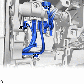
(b) Detach the claw and disconnect the connector housing.
(c) Detach the 2 wire harness clamps.
| (d) w/o Connector Stopper: (1) Release the connector lock lever and disconnect the connector. HINT: Use the same procedure to disconnect the remaining 3 connectors. |
|
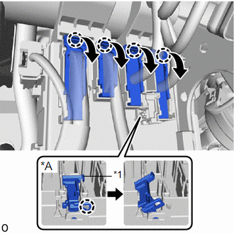
(e) w/ Connector Stopper:
(1) Detach the claw and release the connector stopper.
(2) Release the connector lock lever and disconnect the connector.
HINT:
Use the same procedure to disconnect the remaining 3 connectors.
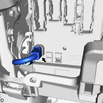
| (f) Disconnect the connector from the lower side of the instrument panel junction block assembly. |
|
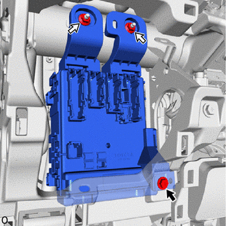
| (g) Remove the bolt, 2 nuts and instrument panel junction block assembly. |
|
| (h) Disconnect the 3 connectors from the multiplex network body ECU (main body ECU). |
|
15. REMOVE MULTIPLEX NETWORK BODY ECU (MAIN BODY ECU)
NOTICE:
- If the multiplex network body ECU (main body ECU) is replaced, replace it with a new one.
- If the multiplex network body ECU (main body ECU) is replaced, refer to the Service Bulletin.
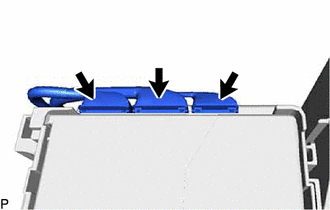
(a) Press the claw of the junction block as shown in the illustration to release the lock.
| *1 | Claw of Junction Block |
 | Protective Tape |
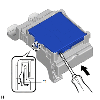
(b) With the junction block lock released, insert a screwdriver with its tip wrapped with protective tape horizontally between the multiplex network body ECU (main body ECU) and junction block.
NOTICE:
Use a screwdriver with a diameter of between 5.0 mm (0.197 in.) and 6.3 mm (0.248 in.) and a length of approximately 90 mm (3.54 in.).
(c) Using the screwdriver, carefully raise the multiplex network body ECU (main body ECU) up to the position where the connector becomes disengaged.
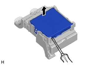
| | Protective Tape |
NOTICE:
- Do not insert the screwdriver opening between the junction block and the connector of the multiplex network body ECU (main body ECU).
- Do not twist the screwdriver to raise the multiplex network body ECU (main body ECU).
(d) Raise the multiplex network body ECU (main body ECU) as shown by the black arrow, and then slide it out as shown by the white arrow in the illustration.
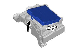
.png) | Raise |
 | Slide Out |
NOTICE:
Do not touch the ECU connector.
READ NEXT:
 Installation
INSTALLATION PROCEDURE 1. INSTALL MULTIPLEX NETWORK BODY ECU (MAIN BODY ECU) NOTICE:
Make sure that no foreign matter gets on the connecting surfaces.
Do not touch the ECU connector.
(a) Inser
SEE MORE:
Headlight Beam Level Control Motor LH Malfunction (B2417,B2418)
DESCRIPTION DTC No. Detection Item DTC Detection Condition Trouble Area B2417 Headlight Beam Level Control Motor LH Malfunction
Power switch on (IG)
Malfunction in headlight leveling motor LH
10 seconds or more
Headlight unit assembly LH B2418 Headlight Bea
Essential information
Emergency flashers
The emergency flashers are used to
warn other drivers when the vehicle
has to be stopped in the road due to
a breakdown, etc.
Operating instructions
Press the switch.
All the turn signal lights will flash. To turn
them off, press the switch once again.
■Emergency
