Lexus NX: Components
COMPONENTS
ILLUSTRATION
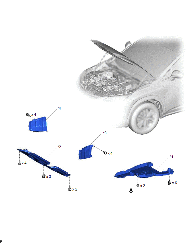
| *1 | FRONT FLOOR COVER CENTER LH | *2 | NO. 1 ENGINE UNDER COVER |
| *3 | REAR ENGINE UNDER COVER LH | *4 | REAR ENGINE UNDER COVER RH |
ILLUSTRATION
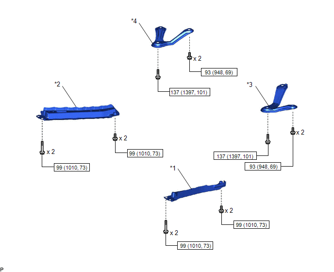
| *1 | FRONT STABILIZER LINK ASSEMBLY LH | *2 | FRONT STABILIZER LINK ASSEMBLY RH |
| *3 | FRONT SUSPENSION MEMBER REAR BRACE LH | *4 | FRONT SUSPENSION MEMBER REAR BRACE RH |
.png) | N*m (kgf*cm, ft.*lbf): Specified | - | - |
ILLUSTRATION
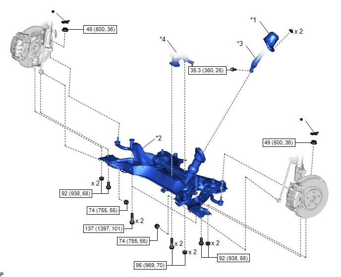
| *1 | COLUMN HOLE COVER SILENCER SHEET | *2 | FRONT SUSPENSION CROSSMEMBER SUB-ASSEMBLY |
| *3 | NO. 2 STEERING INTERMEDIATE SHAFT ASSEMBLY | *4 | ENGINE MOUNTING INSULATOR |
| | N*m (kgf*cm, ft.*lbf): Specified | ● | Non-reusable part |
ILLUSTRATION
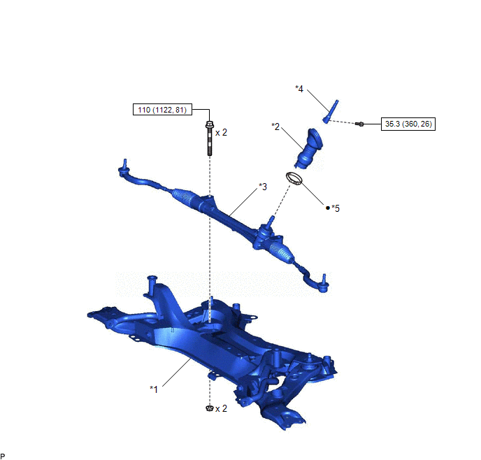
| *1 | FRONT SUSPENSION CROSSMEMBER SUB-ASSEMBLY | *2 | NO. 1 STEERING COLUMN HOLE COVER SUB-ASSEMBLY |
| *3 | STEERING GEAR ASSEMBLY | *4 | STEERING INTERMEDIATE SHAFT |
| *5 | CLAMP | - | - |
| | N*m (kgf*cm, ft.*lbf): Specified | ● | Non-reusable part |
ILLUSTRATION
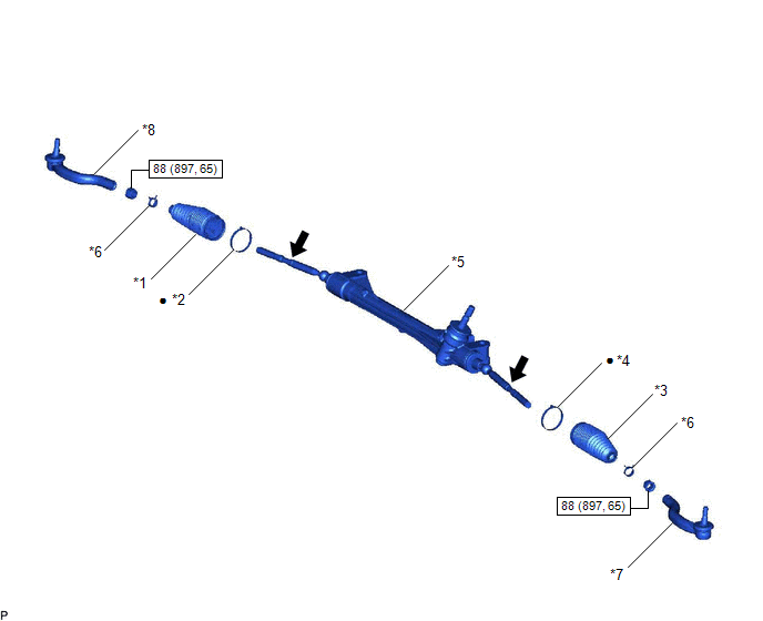
| *1 | NO. 1 STEERING RACK BOOT | *2 | NO. 1 STEERING RACK BOOT CLAMP |
| *3 | NO. 2 STEERING RACK BOOT | *4 | NO. 2 STEERING RACK BOOT CLAMP |
| *5 | STEERING GEAR ASSEMBLY | *6 | STEERING RACK BOOT CLIP |
| *7 | TIE ROD END SUB-ASSEMBLY LH | *8 | TIE ROD END SUB-ASSEMBLY RH |
| | N*m (kgf*cm, ft.*lbf): Specified | ● | Non-reusable part |
.png) | Lithium soap base glycol grease | - | - |
READ NEXT:
 Removal
REMOVAL PROCEDURE 1. PLACE FRONT WHEELS FACING STRAIGHT AHEAD 2. SECURE STEERING WHEEL (a) Secure the steering wheel assembly with the seat belt in order to prevent rotation. HINT: This operation i
Disassembly
DISASSEMBLY PROCEDURE 1. FIX STEERING GEAR ASSEMBLY (a) Using SST, fix the steering gear assembly. SST: 09612-00012 HINT: Apply protective tape to SST before use. *a Protective Tape
Inspection
INSPECTION CAUTION / NOTICE / HINT NOTICE:
When using a vise, place aluminum plates between the part and vise.
When using a vise, do not overtighten it.
PROCEDURE 1. INSPECT TIE ROD END SUB-AS
SEE MORE:
Diagnosis System
DIAGNOSIS SYSTEM DESCRIPTION (a) When troubleshooting a vehicle with the diagnostic system, the only difference from the usual troubleshooting procedure is connecting the Techstream to the vehicle and reading various data output from the multiplex tilt and telescopic ECU. The multiplex tilt and tele
Cooling Fan Ecu
On-vehicle InspectionON-VEHICLE INSPECTION PROCEDURE 1. INSPECT COOLING FAN ECU (a) Check and ensure the following conditions: (1) The power switch is off. (2) The engine coolant temperature is less than 92°C (198°F). (3) The auxiliary battery voltage is between 11 and 14 V. (4) The A/C switch is
