Lexus NX: Removal
REMOVAL
PROCEDURE
1. PLACE FRONT WHEELS FACING STRAIGHT AHEAD
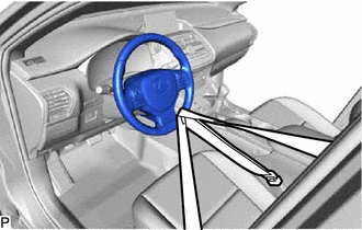
2. SECURE STEERING WHEEL
| (a) Secure the steering wheel assembly with the seat belt in order to prevent rotation. HINT: This operation is useful to prevent damage to the spiral cable. |
|
3. REMOVE COLUMN HOLE COVER SILENCER SHEET
| (a) Fold back the floor carpet, and then remove the 2 clips and column hole cover silencer sheet. |
|
.png)
4. DISCONNECT NO. 2 STEERING INTERMEDIATE SHAFT ASSEMBLY
| (a) Place matchmarks on the sliding yoke of the steering intermediate shaft. |
|
.png)
(b) Remove the bolt and disconnect the No. 2 steering intermediate shaft assembly.
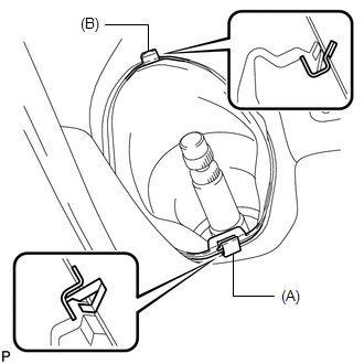
5. DISCONNECT NO. 1 STEERING COLUMN HOLE COVER SUB-ASSEMBLY
| (a) Remove the clip (A), disengage the clip (B) from the body and separate the No. 1 steering column hole cover sub-assembly. NOTICE: Do not damage the clips (A) and (B). |
|
6. REMOVE FRONT WHEELS
Click here .gif)
7. REMOVE NO. 1 ENGINE UNDER COVER
Click here
8. REMOVE FRONT FLOOR COVER CENTER LH
Click here
9. REMOVE REAR ENGINE UNDER COVER LH
Click here
10. REMOVE REAR ENGINE UNDER COVER RH
Click here
11. DISCONNECT TIE ROD END SUB-ASSEMBLY LH
(a) Remove the cotter pin and castle nut.
(b) Using SST, disconnect the tie rod end sub-assembly LH from the steering knuckle.
SST: 09960-20010
09961-02060
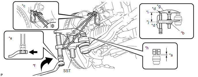
| *a | 1 mm (0.0397 in.) | *b | Nut |
| *c | String | *d | Molybdenum Grease Application Area |
| *e | Place the wrench here | *f | Turn |
| *g | SST Number | *h | Spacer B |
| *i | Body | *j | Claw |
CAUTION:
Apply molybdenum grease to the bolt threads and the tip of SST.
NOTICE:
- Make sure to tie the string of SST to the vehicle to prevent SST from dropping.
- As the ball joint dust cover may be damaged, adjust SST with the center nut so that the body and claw are parallel.
- Do not damage the ball joint boot of the tie rod end.
- Do not damage the steering knuckle.
- Do not damage the front disc brake dust cover.
12. DISCONNECT TIE ROD END SUB-ASSEMBLY RH
HINT:
Use the same procedure described for the LH side.
13. DISCONNECT FRONT STABILIZER LINK ASSEMBLY LH
Click here
14. DISCONNECT FRONT STABILIZER LINK ASSEMBLY RH
HINT:
Use the same procedure described for the LH side.
15. REMOVE FRONT SUSPENSION MEMBER REINFORCEMENT LH
Click here
16. REMOVE FRONT SUSPENSION MEMBER REINFORCEMENT RH
HINT:
Use the same procedure described for the LH side.
17. REMOVE FRONT SUSPENSION MEMBER REAR BRACE LH
Click here
18. REMOVE FRONT SUSPENSION MEMBER REAR BRACE RH
HINT:
Use the same procedure described for the LH side.
19. REMOVE FRONT SUSPENSION CROSSMEMBER SUB-ASSEMBLY
Click here
20. REMOVE NO. 1 STEERING COLUMN HOLE COVER SUB-ASSEMBLY
(a) Remove the clamp.
| (b) Remove the No. 1 steering column hole cover sub-assembly from the steering gear assembly. |
|
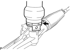
21. REMOVE STEERING INTERMEDIATE SHAFT
| (a) Place matchmarks on the steering intermediate shaft and steering gear assembly. |
|
(b) Remove the bolt and steering intermediate shaft from the steering gear assembly.
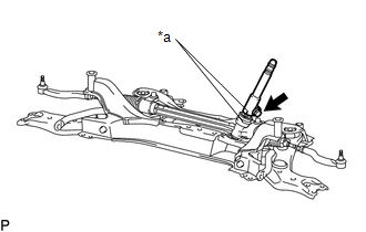
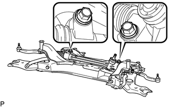
22. REMOVE STEERING GEAR ASSEMBLY
| (a) Remove the 2 bolts, 2 nuts and steering gear assembly from the front suspension crossmember sub-assembly. NOTICE: Because the nut has its own stopper, do not turn the nut. Loosen the bolt with the nut fixed in place. |
|
READ NEXT:
 Disassembly
DISASSEMBLY PROCEDURE 1. FIX STEERING GEAR ASSEMBLY (a) Using SST, fix the steering gear assembly. SST: 09612-00012 HINT: Apply protective tape to SST before use. *a Protective Tape
Inspection
INSPECTION CAUTION / NOTICE / HINT NOTICE:
When using a vise, place aluminum plates between the part and vise.
When using a vise, do not overtighten it.
PROCEDURE 1. INSPECT TIE ROD END SUB-AS
Reassembly
REASSEMBLY PROCEDURE 1. INSTALL NO. 2 STEERING RACK BOOT (a) Apply lithium soap base glycol grease to the inside of the steering rack end. *1 Rack Housing *2 Steering Rack End
SEE MORE:
Steering Angle Midpoint Initial Setting Incomplete (C1AEA)
DESCRIPTION When the clearance warning ECU assembly detects that the steering angle neutral point memorization is incomplete during self-diagnosis, C1AEA is stored. DTC No. Detection Item DTC Detection Condition Trouble Area C1AEA Steering Angle Midpoint Initial Setting Incomplete S
Components
COMPONENTS ILLUSTRATION *1 CLEARANCE LIGHT ASSEMBLY LH *2 CLEARANCE LIGHT ASSEMBLY RH *3 FRONT BUMPER GUARD ASSEMBLY *4 HOOD TO FRONT END PANEL SEAL *5 NO. 3 ENGINE ROOM WIRE *6 RADIATOR GRILLE SUB-ASSEMBLY *7 OUTSIDE MOULDING RETAINER - - ILLUSTRATION
