Lexus NX: Components
COMPONENTS
ILLUSTRATION
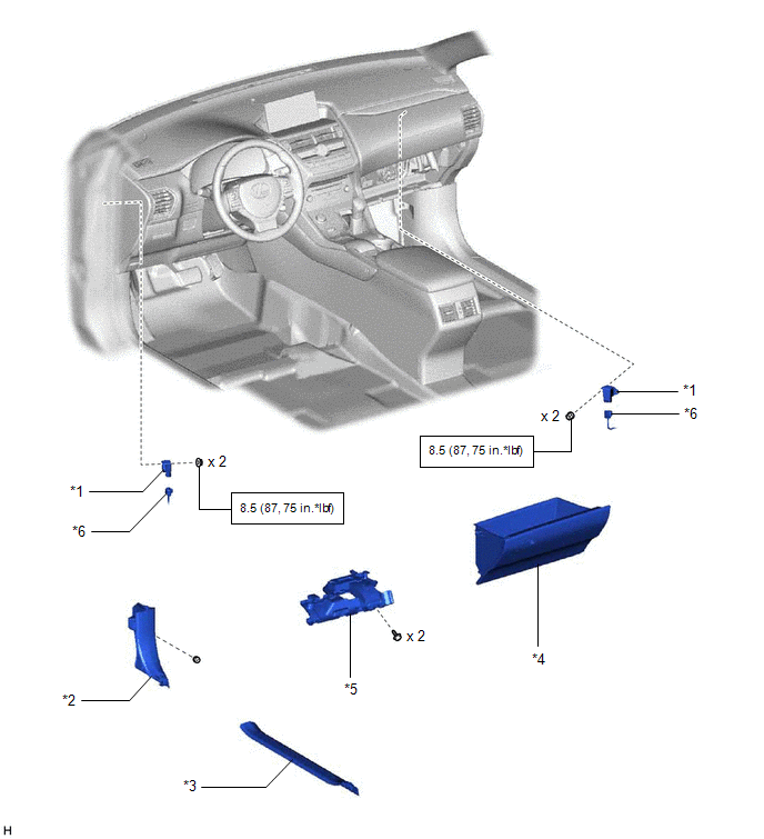
| *1 | ACCELERATION SENSOR | *2 | COWL SIDE TRIM BOARD LH |
| *3 | DOOR SCUFF PLATE ASSEMBLY LH | *4 | GLOVE COMPARTMENT DOOR ASSEMBLY |
| *5 | NO. 1 INSTRUMENT PANEL UNDER COVER SUB-ASSEMBLY | *6 | CONNECTOR |
.png) | N*m (kgf*cm, ft.*lbf): Specified torque | - | - |
READ NEXT:
 Removal
REMOVAL PROCEDURE 1. REMOVE DOOR SCUFF PLATE ASSEMBLY LH Click here 2. REMOVE COWL SIDE TRIM BOARD LH Click here 3. REMOVE NO. 1 INSTRUMENT PANEL UNDER COVER SUB-ASSEMBLY Click here 4. REMOVE GL
Inspection
INSPECTION PROCEDURE 1. INSPECT ACCELERATION SENSOR (a) Connect 3 1.5 V dry cell batteries in series. (b) Connect a positive (+) lead from the batteries to terminal 3 (SGB) and a negative (-) lead to
Installation
INSTALLATION PROCEDURE 1. INSTALL ACCELERATION SENSOR (a) for RH side: (1) Install the acceleration sensor with the 2 nuts. Torque: 8.5 N·m {87 kgf·cm, 75 in·lbf} NOTICE:
Avoid any impact to th
SEE MORE:
Brake Warning Light Remains ON
DESCRIPTION The skid control ECU (brake booster with master cylinder assembly) is connected to the combination meter assembly via CAN communication. If any of the following is detected, the brake warning light / red (malfunction) remains on:
The skid control ECU (brake booster with master cylinde
Sub Radiator
RemovalREMOVAL PROCEDURE 1. REMOVE NO. 1 ENGINE UNDER COVER ASSEMBLY Click here 2. DRAIN COOLANT (for Inverter Coolant) Click here 3. REMOVE UPPER RADIATOR SUPPORT SUB-ASSEMBLY Click here 4. REMOVE NO. 2 FAN SHROUD Click here 5. REMOVE RADIATOR ASSEMBLY (for Inverter Coolant) (a) Slide
© 2016-2026 Copyright www.lexunx.com
