Lexus NX: Components
Lexus NX Service Manual / Vehicle Exterior / Door / Hatch / Hood Lock Control Cable Assembly / Components
COMPONENTS
ILLUSTRATION
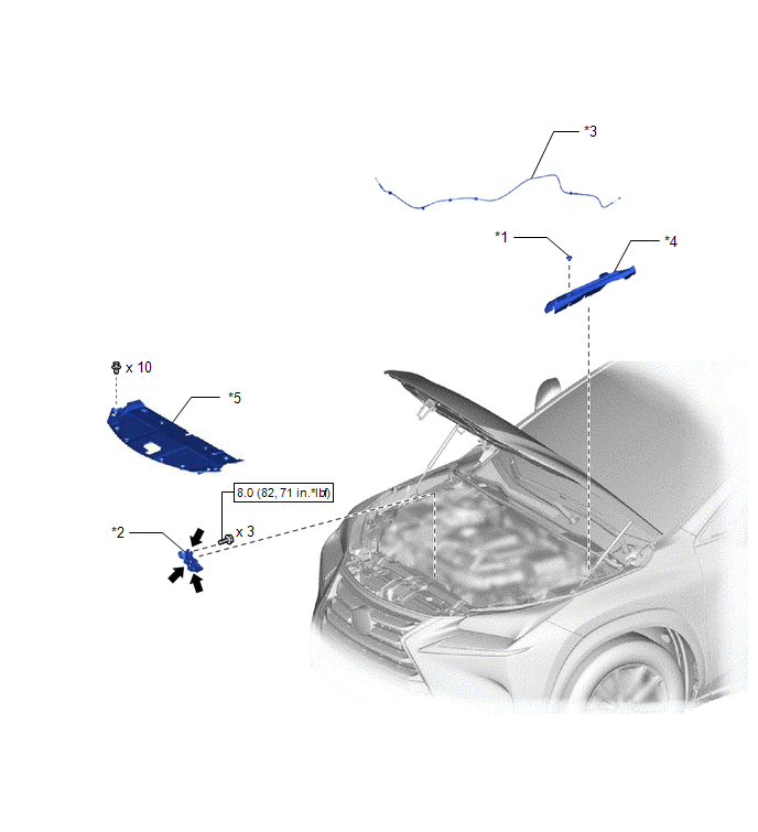
| *1 | CENTER HOOD CUSHION | *2 | HOOD LOCK ASSEMBLY |
| *3 | HOOD LOCK CONTROL CABLE ASSEMBLY | *4 | HOOD TO FRONT FENDER SEAL LH |
| *5 | RADIATOR SUPPORT OPENING COVER | - | - |
.png) | N*m (kgf*cm, ft.*lbf): Specified torque | .png) | MP grease |
ILLUSTRATION
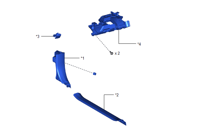
| *1 | COWL SIDE TRIM BOARD LH | *2 | DOOR SCUFF PLATE ASSEMBLY LH |
| *3 | HOOD LOCK CONTROL LEVER SUB-ASSEMBLY | *4 | NO. 1 INSTRUMENT PANEL UNDER COVER SUB-ASSEMBLY |
READ NEXT:
 Removal
REMOVAL PROCEDURE 1. REMOVE RADIATOR SUPPORT OPENING COVER Click here 2. REMOVE HOOD LOCK ASSEMBLY Click here 3. REMOVE CENTER HOOD CUSHION (a) Detach the 2 claws and remove the center hood cush
Installation
INSTALLATION PROCEDURE 1. INSTALL HOOD LOCK CONTROL CABLE ASSEMBLY (a) Tie the string that was passed through the engine compartment room to the end of the hood lock control cable assembly as shown
Hood Support
ComponentsCOMPONENTS ILLUSTRATION *1 HOOD STAY BRACKET LH *2 HOOD SUPPORT ASSEMBLY *3 STOP RING - - N*m (kgf*cm, ft.*lbf): Specified torque - - RemovalREMOVAL CAUTI
SEE MORE:
Components
COMPONENTS ILLUSTRATION *1 BATTERY SERVICE HOLE COVER *2 HYBRID BATTERY SERVICE PLUG COVER *3 SERVICE PLUG GRIP - - N*m (kgf*cm, ft.*lbf): Specified torque - - ILLUSTRATION *1 NO. 1 ENGINE UNDER COVER ASSEMBLY *2 REAR ENGINE UNDER COVER LH *3 REAR EN
How To Proceed With Troubleshooting
CAUTION / NOTICE / HINT HINT:
Use the following procedure to troubleshoot the LEXUS ENFORM system.
*: Use the Techstream.
PROCEDURE 1. VEHICLE BROUGHT TO WORKSHOP
NEXT 2. CHECK THE CUSTOMER'S CONTRACT STATUS (a) Check if the satellite radio and LEXUS ENFORM
© 2016-2026 Copyright www.lexunx.com
