Lexus NX: Removal
REMOVAL
PROCEDURE
1. REMOVE RADIATOR SUPPORT OPENING COVER
Click here .gif)
2. REMOVE HOOD LOCK ASSEMBLY
Click here
3. REMOVE CENTER HOOD CUSHION
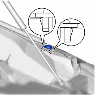
(a) Detach the 2 claws and remove the center hood cushion.
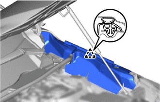
4. REMOVE HOOD TO FRONT FENDER SEAL LH
| (a) Detach the clip and remove the hood to front fender seal LH. |
|
5. REMOVE DOOR SCUFF PLATE ASSEMBLY LH
Click here
6. REMOVE COWL SIDE TRIM BOARD LH
Click here
7. REMOVE NO. 1 INSTRUMENT PANEL UNDER COVER SUB-ASSEMBLY
Click here
8. REMOVE HOOD LOCK CONTROL LEVER SUB-ASSEMBLY
| (a) Detach the 3 claws and disconnect the hood lock control lever sub-assembly. |
|
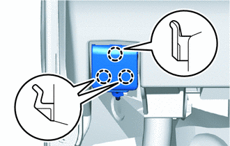
| (b) Disconnect the hood lock control cable assembly and remove the hood lock control lever sub-assembly. |
|
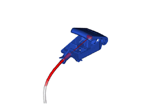
9. REMOVE HOOD LOCK CONTROL CABLE ASSEMBLY
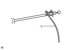
| (a) Tie a string to the end of the hood lock control cable assembly as shown in the illustration. HINT: Use a length of string long enough to pass through the engine compartment. |
|
(b) Detach each clamp, and then pull out the hood lock control cable assembly from the vehicle body.
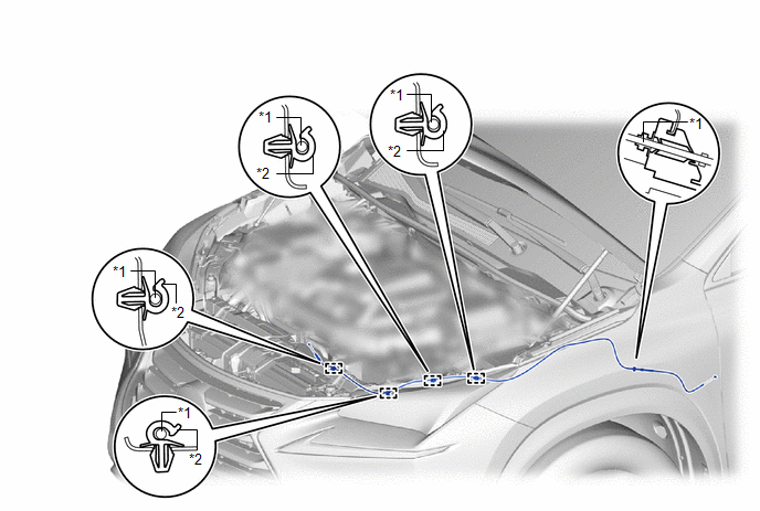
| *1 | Hood Lock Control Cable Assembly | *2 | Clamp |
(c) Untie the string from the hood lock control cable assembly.
READ NEXT:
 Installation
INSTALLATION PROCEDURE 1. INSTALL HOOD LOCK CONTROL CABLE ASSEMBLY (a) Tie the string that was passed through the engine compartment room to the end of the hood lock control cable assembly as shown
Hood Support
ComponentsCOMPONENTS ILLUSTRATION *1 HOOD STAY BRACKET LH *2 HOOD SUPPORT ASSEMBLY *3 STOP RING - - N*m (kgf*cm, ft.*lbf): Specified torque - - RemovalREMOVAL CAUTI
SEE MORE:
Motor Electronics Coolant Temperature Sensor Circuit Range / Performance (P0A01-726,P0A04-725)
DTC SUMMARY MALFUNCTION DESCRIPTION These DTCs indicate the temperature sensor value is abnormal. The cause of this malfunction may be one of the following: Area Main Malfunction Description Step Inverter low-voltage circuit The connectors are not connected properly 2 Hybrid cooli
Terminals Of Ecu
TERMINALS OF ECU NOTICE:
After turning the power switch off, waiting time may be required before disconnecting the cable from the negative (-) auxiliary battery terminal.
Click here
When disconnecting and reconnecting the auxiliary battery.
Click here HINT: When disconnecting and reconnecti
