Lexus NX: Components
COMPONENTS
ILLUSTRATION
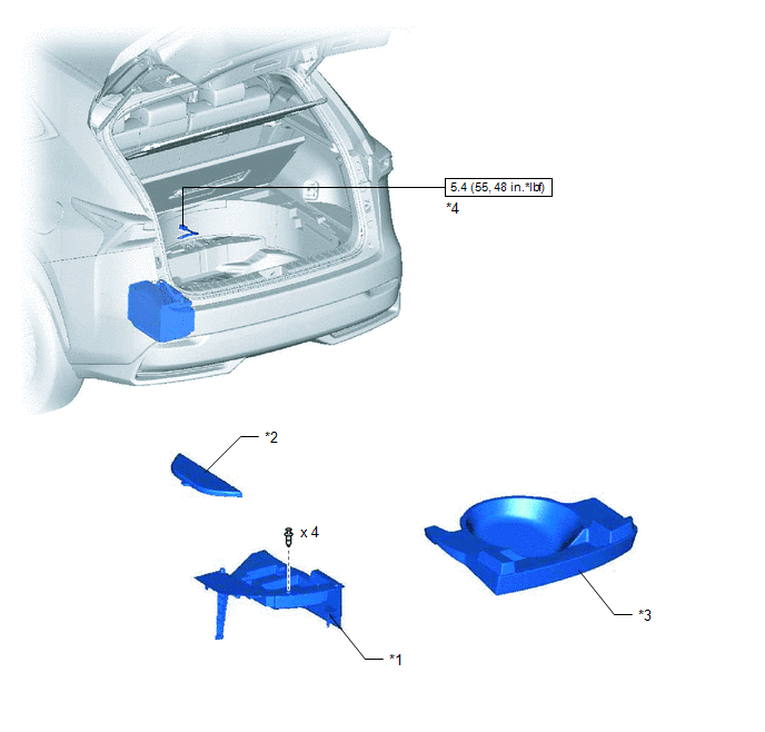
| *1 | DECK FLOOR BOX LH | *2 | NO. 3 DECK BOARD SUB-ASSEMBLY |
| *3 | REAR DECK FLOOR BOX | *4 | NEGATIVE AUXILIARY BATTERY TERMINAL |
.png) | N*m (kgf*cm, ft.*lbf): Specified torque | - | - |
ILLUSTRATION
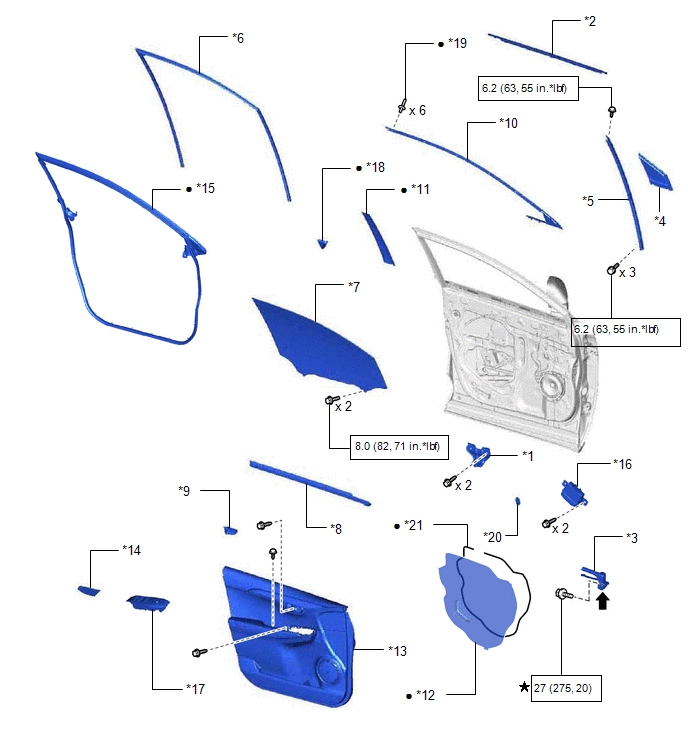
| *1 | FRONT DOOR ARMREST SET BRACKET LH | *2 | FRONT DOOR BELT MOULDING ASSEMBLY LH |
| *3 | FRONT DOOR CHECK ASSEMBLY LH | *4 | FRONT DOOR FIX WINDOW GLASS LH |
| *5 | FRONT DOOR FRONT LOWER FRAME SUB-ASSEMBLY LH | *6 | FRONT DOOR GLASS RUN LH |
| *7 | FRONT DOOR GLASS SUB-ASSEMBLY LH | *8 | FRONT DOOR INNER GLASS WEATHERSTRIP LH |
| *9 | FRONT DOOR INSIDE HANDLE BEZEL PLUG LH | *10 | FRONT DOOR OUTSIDE MOULDING SUB-ASSEMBLY LH |
| *11 | FRONT DOOR REAR WINDOW FRAME MOULDING LH | *12 | FRONT DOOR SERVICE HOLE COVER LH |
| *13 | FRONT DOOR TRIM BOARD SUB-ASSEMBLY LH | *14 | FRONT DOOR TRIM COVER LH |
| *15 | FRONT DOOR WEATHERSTRIP LH | *16 | OUTER MIRROR CONTROL ECU ASSEMBLY |
| *17 | POWER WINDOW REGULATOR MASTER SWITCH ASSEMBLY WITH FRONT DOOR ARMREST BASE PANEL | *18 | UPPER DOOR FRAME GARNISH LH |
| *19 | RIVET | *20 | HOLE PLUG |
| *21 | BUTYL TAPE | - | - |
| | N*m (kgf*cm, ft.*lbf): Specified torque | ★ | Precoated part |
| ● | Non-reusable part | .png) | MP grease |
READ NEXT:
 Removal
REMOVAL CAUTION / NOTICE / HINT HINT:
Use the same procedure for the RH and LH sides.
The procedure listed below is for the LH side.
PROCEDURE 1. PRECAUTION NOTICE: After the power switch off
Installation
INSTALLATION CAUTION / NOTICE / HINT HINT:
Use the same procedure for the RH and LH sides.
The procedure listed below is for the LH side.
PROCEDURE 1. INSTALL FRONT DOOR OUTSIDE MOULDING SUB-A
SEE MORE:
AVC-LAN Circuit
DESCRIPTION Each audio system component connected to the AVC-LAN (communication bus) transfers switch signals using the audio visual communication local area network. If a short to +B or short to ground occurs in the AVC-LAN, the audio system will not function normally because communication is not p
Front Passenger Side Door Entry Lock and Unlock Functions do not Operate
DESCRIPTION If the entry lock and unlock functions do not operate for the front passenger door only, the request code may not be being transmitted from the front passenger door or the front door outside handle assembly (for front passenger door) (touch sensor) may be malfunctioning. If the entry fun
