Lexus NX: Removal
REMOVAL
CAUTION / NOTICE / HINT
HINT:
- Use the same procedure for the RH and LH sides.
- The procedure listed below is for the LH side.
PROCEDURE
1. PRECAUTION
NOTICE:
After the power switch off is turned off, there may be a waiting time before disconnecting the auxiliary negative (-) battery terminal.
Click here .gif)
2. REMOVE NO. 3 DECK BOARD SUB-ASSEMBLY
Click here
3. REMOVE REAR DECK FLOOR BOX
Click here
4. REMOVE DECK FLOOR BOX LH
Click here
5. DISCONNECT CABLE FROM NEGATIVE AUXILIARY BATTERY TERMINAL
Click here
6. REMOVE FRONT DOOR TRIM COVER LH
Click here
7. REMOVE FRONT DOOR INSIDE HANDLE BEZEL PLUG LH
Click here
8. REMOVE POWER WINDOW REGULATOR MASTER SWITCH ASSEMBLY WITH FRONT DOOR ARMREST BASE PANEL
Click here
9. REMOVE FRONT DOOR TRIM BOARD SUB-ASSEMBLY LH
Click here
10. REMOVE FRONT DOOR INNER GLASS WEATHERSTRIP LH
Click here
11. REMOVE FRONT DOOR ARMREST SET BRACKET LH
Click here
12. REMOVE FRONT DOOR SERVICE HOLE COVER LH
Click here
13. REMOVE FRONT DOOR GLASS RUN LH
Click here
14. REMOVE FRONT DOOR GLASS SUB-ASSEMBLY LH
Click here
15. REMOVE FRONT DOOR BELT MOULDING ASSEMBLY LH
Click here
16. REMOVE OUTER MIRROR CONTROL ECU ASSEMBLY
Click here
17. DISCONNECT FRONT DOOR CHECK ASSEMBLY LH
Click here
18. REMOVE FRONT DOOR WEATHERSTRIP LH
Click here
19. REMOVE UPPER DOOR FRAME GARNISH LH
Click here
20. REMOVE FRONT DOOR FRONT LOWER FRAME SUB-ASSEMBLY LH
Click here
21. REMOVE FRONT DOOR FIX WINDOW GLASS LH
Click here
22. REMOVE FRONT DOOR REAR WINDOW FRAME MOULDING LH
HINT:
When removing front door rear window frame moulding LH, heat the front door panel and front door rear window frame moulding LH using a heat light.
Standard:
| Item | Temperature |
|---|---|
| Front Door Panel | 40 to 60°C (104 to 140°F) |
| Front Door Rear Window Frame Moulding LH | 20 to 30°C (68 to 86°F) |
NOTICE:
Do not heat the front door panel or front door rear window frame moulding LH excessively.
(a) Put protective tape around the front door rear window frame moulding LH.
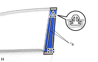
| *a | Double-sided Tape |
.png) | Protective Tape |
(b) Using moulding remover D, detach the clip.
(c) Detach the double-sided tape, and then detach the guide and remove the front door rear window frame moulding LH.
23. REMOVE FRONT DOOR OUTSIDE MOULDING SUB-ASSEMBLY LH
(a) Put a 4 mm (0.157 in.) drill bit into a drill.
(b) Wind tape around the drill bit approximately 5 mm (0.197 in.) from the tip of the drill as shown in the illustration.
HINT:
Tape the 4 mm (0.157 in.) drill bit to prevent the drill bit from going too deep.
(c) Lightly press the drill against the 6 rivets and drill off the flanges of the 6 rivets.
CAUTION:
Be careful of the drilled rivet as it may become hot.
NOTICE:
- Pressing the drill too firmly will cause the rivet to turn and result in the rivet not being drilled through.
- Do not pry the rivet with the drill because this may cause damage to the installation holes of the rivet or the drill bit.
(d) Detach the 3 claws and remove the front door outside moulding sub-assembly LH.
(e) Using a vacuum cleaner, remove the rivet fragments and shavings from the drilled area.
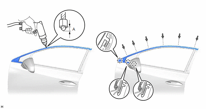
Standard:
| Area | Specified Condition |
|---|---|
| A | 5 mm (0.197 in.) |
READ NEXT:
 Installation
INSTALLATION CAUTION / NOTICE / HINT HINT:
Use the same procedure for the RH and LH sides.
The procedure listed below is for the LH side.
PROCEDURE 1. INSTALL FRONT DOOR OUTSIDE MOULDING SUB-A
Components
COMPONENTS ILLUSTRATION *A for Sport Package - - *1 BACK DOOR NAME PLATE *2 BACK DOOR NO. 2 NAME PLATE *3 REAR BODY NO. 4 NAME PLATE *4 SYMBOL EMBLEM ● Non-reusab
SEE MORE:
Refrigerant Shortage (B14B8)
DESCRIPTION This DTC is stored if the amount of refrigerant in the air conditioning system is insufficient. The air conditioning amplifier assembly receives the ambient temperature signal, refrigerant pressure signal etc. from various sensors. Based on these signals, the air conditioning amplifier a
Lost Communication With TCM (U0101,U0122,U0142,U0155,U0327,U1114,U1117)
DESCRIPTION These DTCs are stored when a malfunction occurs in the CAN communication circuit. DTC No. Detection Item Trouble Area U0101 Lost Communication With TCM
CAN communication system
ECM
Multiplex network door ECU
U0122 Lost Communication With Vehicle Dynamics Co
