Lexus NX: Inspection
INSPECTION
PROCEDURE
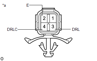
1. INSPECT CLEARANCE LIGHT ASSEMBLY LH
| (a) Apply battery voltage to the connector and check the light illumination condition. OK:
If the result is not as specified, replace the clearance light assembly LH. |
|
2. INSPECT CLEARANCE LIGHT ASSEMBLY RH
| (a) Apply battery voltage to the connector and check the light illumination condition. OK:
If the result is not as specified, replace the clearance light assembly RH. |
|

READ NEXT:
 Reassembly
REASSEMBLY CAUTION / NOTICE / HINT HINT:
Use the same procedure for the RH and LH sides.
The procedure listed below is for the LH side.
PROCEDURE 1. INSTALL FRONT TURN SIGNAL LIGHT BULB (a) In
Installation
INSTALLATION CAUTION / NOTICE / HINT HINT:
Use the same procedure for the RH and LH sides.
The procedure described below is for the LH side.
PROCEDURE 1. INSTALL CLEARANCE LIGHT ASSEMBLY LH (a
SEE MORE:
Tachometer Malfunction
DESCRIPTION In this circuit, the combination meter assembly receives engine speed signals from the hybrid vehicle control ECU via the CAN communication system. The combination meter assembly displays the engine speed calculated based on the data received from the hybrid vehicle control ECU. WIRING D
Diagnosis System
DIAGNOSIS SYSTEM CHECK DLC3 (a) Check the DLC3. Click here FUNCTION OF PASSENGER AIRBAG ON/OFF INDICATOR (a) Initial check (1) Turn the power switch on (IG). (2) The passenger airbag ON/OFF indicator comes on for approximately 4 seconds, and then goes off for approximately 2 seconds. (3) Approxim
