Lexus NX: Components
COMPONENTS
ILLUSTRATION
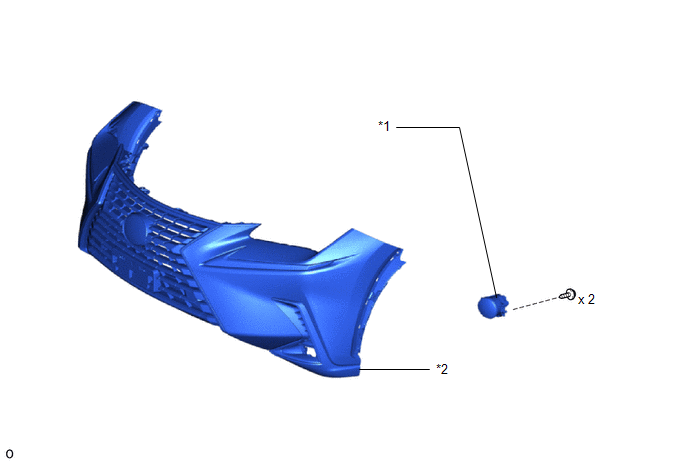
| *1 | FOG LIGHT ASSEMBLY LH | *2 | FRONT BUMPER ASSEMBLY |
READ NEXT:
 Removal
REMOVAL CAUTION / NOTICE / HINT HINT:
Use the same procedure for the RH and LH sides.
The procedure described below is for the LH side.
PROCEDURE 1. REMOVE FRONT BUMPER ASSEMBLY Click here 2
Inspection
INSPECTION PROCEDURE 1. INSPECT FOG LIGHT ASSEMBLY LH (a) Apply battery voltage to the connector and check the light illumination condition. OK: Condition Specified Condition Battery posi
Adjustment
ADJUSTMENT CAUTION / NOTICE / HINT HINT:
Use the same procedure for the RH and LH sides.
The procedure listed below is for the LH side.
It is possible that a fog light assembly is incorrectly i
SEE MORE:
Inspection
INSPECTION PROCEDURE 1. INSPECT TILT AND TELESCOPIC SWITCH (a) Measure the resistance according to the value(s) in the table below. Standard Resistance: Tester Connection Switch Condition Specified Condition 1 (VC) - 3 (MSW) Tilt up 342 to 378 Ω Tilt down 1890.5 to 2089.5 Î
On-vehicle Inspection
ON-VEHICLE INSPECTION CAUTION / NOTICE / HINT CAUTION: Be sure to follow the correct removal and installation procedures of the rear airbag sensors. PROCEDURE 1. INSPECT REAR AIRBAG SENSOR (for Vehicle not Involved in Collision) (a) Perform a diagnostic system check. Click here 2. INSPECT REAR AI
© 2016-2026 Copyright www.lexunx.com
