Lexus NX: Components
COMPONENTS
ILLUSTRATION
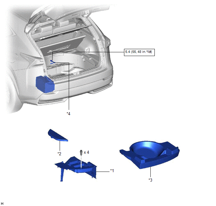
| *1 | DECK FLOOR BOX LH | *2 | NO. 3 DECK BOARD SUB-ASSEMBLY |
| *3 | REAR DECK FLOOR BOX | *4 | AUXILIARY BATTERY NEGATIVE TERMINAL |
.png) | N*m (kgf*cm, ft.*lbf): Specified torque | - | - |
ILLUSTRATION
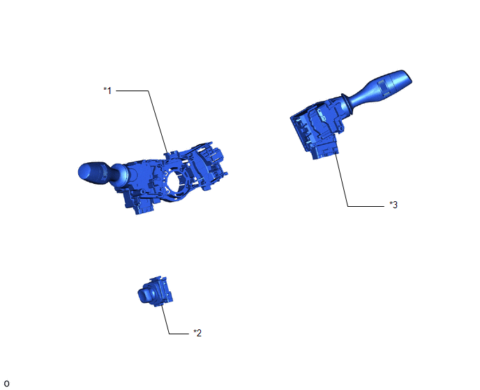
| *1 | HEADLIGHT DIMMER SWITCH ASSEMBLY | *2 | TILT AND TELESCOPIC SWITCH |
| *3 | WINDSHIELD WIPER SWITCH ASSEMBLY | - | - |
READ NEXT:
 Removal
REMOVAL PROCEDURE 1. REMOVE NO. 3 DECK BOARD SUB-ASSEMBLY Click here 2. REMOVE REAR DECK FLOOR BOX Click here 3. REMOVE DECK FLOOR BOX LH Click here 4. PRECAUTION CAUTION: Be sure to read Precau
Inspection
INSPECTION PROCEDURE 1. INSPECT HEADLIGHT DIMMER SWITCH ASSEMBLY (a) Inspect the light control switch. (1) Measure the resistance according to the value(s) in the table below. Standard Resistance:
Installation
INSTALLATION PROCEDURE 1. INSTALL HEADLIGHT DIMMER SWITCH ASSEMBLY (a) Attach the 2 claws to install the headlight dimmer switch assembly. (b) Connect the connector. 2. INSTALL TILT AND TELESCOPIC SWI
SEE MORE:
How To Proceed With Troubleshooting
CAUTION / NOTICE / HINT HINT:
Use the following procedure to troubleshoot the telematics system.
*: Use the Techstream.
PROCEDURE 1. VEHICLE BROUGHT TO WORKSHOP
NEXT 2. CUSTOMER PROBLEM ANALYSIS HINT:
In troubleshooting, confirm that the problem symptoms
Ignition Coil "A" Primary / Secondary Circuit (P0351-P0354)
DESCRIPTION HINT:
These DTCs indicate malfunctions relating to the primary circuit.
If DTC P0351 is output, check the No. 1 ignition coil assembly (No. 1 cylinder) circuit.
If DTC P0352 is output, check the No. 2 ignition coil assembly (No. 2 cylinder) circuit.
If DTC P0353 is output, check
© 2016-2026 Copyright www.lexunx.com
