Lexus NX: Inspection

INSPECTION

PROCEDURE

1. INSPECT HEADLIGHT DIMMER SWITCH ASSEMBLY

(a) Inspect the light control switch.

(1) Measure the resistance according to the value(s) in the table below.

Standard Resistance:

Tester Connection

Switch Condition

Specified Condition

*1: w/ Light Control Switch Off Position

*2: w/ Light control switch DRL OFF Position

18 (T) - 15 (EL)

Light control switch off*1

Light control switch DRL OFF*2

10 kΩ or higher

20 (A) - 15 (EL)

19 (H) - 15 (EL)

20 (A) - 15 (EL)

Light control switch AUTO position

Below 1 Ω

18 (T) - 15 (EL)

Light control switch tail position

Below 1 Ω

18 (T) - 15 (EL)

Light control switch head position

Below 1 Ω

19 (H) - 15 (EL)

HINT:

If the result is not as specified, replace the headlight dimmer switch assembly.

*a

Component without harness connected

(Headlight Dimmer Switch Assembly)

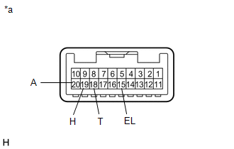
(b) Inspect the headlight dimmer switch.

(1) Measure the resistance according to the value(s) in the table below.

Standard Resistance:

Tester Connection

Switch Condition

Specified Condition

17 (HF) - 15 (EL)

Headlight dimmer switch flash position

Below 1 Ω

14 (HU) - 15 (EL)

14 (HU) - 15 (EL)

Headlight dimmer switch high position

Below 1 Ω

HINT:

If the result is not as specified, replace the headlight dimmer switch assembly.

*a

Component without harness connected

(Headlight Dimmer Switch Assembly)

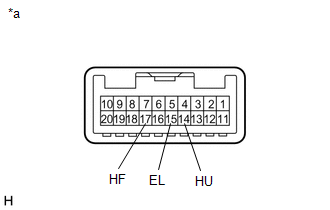
(c) Inspect the turn signal light switch.

(1) Measure the resistance according to the value(s) in the table below.

Standard Resistance:

Tester Connection

Switch Condition

Specified Condition

12 (TR) - 15 (EL)

Turn signal switch neutral position

10 kΩ or higher

11 (TL) - 15 (EL)

12 (TR) - 15 (EL)

Turn signal switch right turn position

(self cancel condition)

Below 1 Ω

12 (TR) - 15 (EL)

Turn signal switch right turn position

(cancel ratchet operation condition)

Below 1 Ω

12 (TR) - 13 (CR)

13 (CR) - 15 (EL)

11 (TL) - 15 (EL)

Turn signal switch left turn position

(self cancel condition)

Below 1 Ω

11 (TL) - 15 (EL)

Turn signal switch in left turn position

(cancel ratchet operation condition)

Below 1 Ω

11 (TL) - 13 (CR)

13 (CR) - 15 (EL)

HINT:

  • If the result is not as specified, replace the headlight dimmer switch assembly.
  • The self cancel condition indicates when the turn signal switch returns to the neutral position when releasing your hand from the switch (switch is operated within 7°).
  • The cancel ratchet operation condition indicates the condition when the turn signal switch does not return to the neutral position even when releasing your hand (switch operation is 12°).

*a

Component without harness connected

(Headlight Dimmer Switch Assembly)

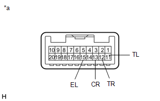
(d) Inspect the front fog light switch.

(1) Measure the resistance according to the value(s) in the table below.

Standard Resistance:

Tester Connection

Switch Condition

Specified Condition

9 (BFG) - 8 (LFG)

Front fog light switch off

10 kΩ or higher

9 (BFG) - 8 (LFG)

Front fog light switch on

Below 1 Ω

HINT:

If the result is not as specified, replace the headlight dimmer switch assembly.

*a

Component without harness connected

(Headlight Dimmer Switch Assembly)

READ NEXT:

 Installation

INSTALLATION PROCEDURE 1. INSTALL HEADLIGHT DIMMER SWITCH ASSEMBLY (a) Attach the 2 claws to install the headlight dimmer switch assembly. (b) Connect the connector. 2. INSTALL TILT AND TELESCOPIC SWI

 Headlight Ecu

 Precaution

PRECAUTION NOTICE: When disassembling the headlight assembly, use static electricity countermeasures SST (desktop antistatic mat set) and observe all precautions to prevent damage to the system by ele

SEE MORE:

 Cold Start Idle Air Control System Performance (P050A)

MONITOR DESCRIPTION This monitor will run when the engine is started at an engine coolant temperature of -10 to 50°C (14 to 122°F). The DTC will be stored after the engine idles for 13 seconds (2 trip detection logic). The DTC is designed to monitor the idle air control at cold start. When the eng

 Compass

The compass on the inside rear view mirror indicates the direction in which the vehicle is heading. Operation and displays To turn the compass on or off, press the button for more than 3 seconds. Directions are displayed as follows: ■Conditions unfavorable to correct operation The com

© 2016-2024 Copyright www.lexunx.com