Lexus NX: Disassembly
Lexus NX Service Manual / Vehicle Exterior / Lighting (ext) / Rear Combination Light Assembly / Disassembly
DISASSEMBLY
PROCEDURE
1. PRECAUTION
NOTICE:
-
Be sure to read Precaution thoroughly before servicing.
Click here
.gif)
- Handle components indoors as much as possible to prevent foreign matter from entering and adhering to rear combination light assembly components.
- Do not reuse parts which have reduced fastening ability due to thread damage.
- Do not touch the inner surface of the lens and metallic surfaces as much as possible, or they may become dirty
- Do not allow metallic surfaces to become dirty, as such surfaces become damaged even if they are only lightly wiped with a soft cloth.
- When installing components, make sure that the wire harness is not pinched or pulled.
- Do not use solvent to clean components. Only clean them with a dry cloth.
HINT:
- Use the same procedure for the RH and LH sides.
- The procedure listed below is for the LH side.
2. REMOVE REAR COMBINATION LIGHT RETAINER LH
| (a) Detach the wire harness clamp. |
|
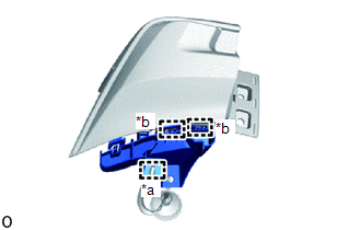
(b) Detach the 2 guides and remove the rear combination light retainer LH.
3. REMOVE REAR COMBINATION LIGHT SOCKET AND WIRE SUB-ASSEMBLY LH
NOTICE:
- Prevention of static electricity is required during this procedure.
- Use static electricity countermeasures SST (desktop anti-static mat set) and observe all precautions to prevent damage to the system by electrostatic discharge (ESD).
- Perform work using clean rubber gloves.
- Do not touch the rear combination light socket and wire sub-assembly LH connector with bare hands.
SST: 09890-47010
09891-04010
09891-04020
09891-04030
09891-04040
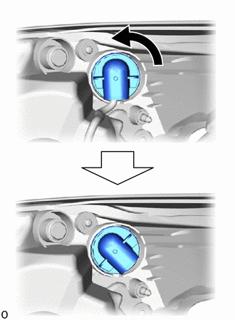
| (a) Turn the connector cap counterclockwise until it stops to disconnect the connector cap. |
|
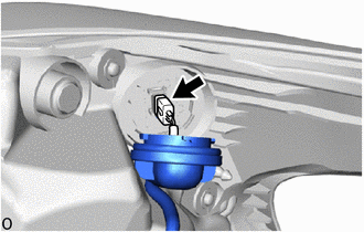
| (b) Disconnect the connector. |
|
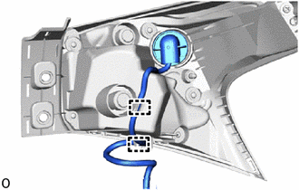
| (c) Detach the 2 wire harness clamps and remove the rear combination light socket and wire sub-assembly LH. |
|
READ NEXT:
 Inspection
INSPECTION PROCEDURE 1. INSPECT REAR COMBINATION LIGHT ASSEMBLY LH (a) Apply battery voltage to the connector and check the light illumination condition. OK: Battery Connection Specified Cond
Reassembly
REASSEMBLY CAUTION / NOTICE / HINT HINT:
Use the same procedure for the RH and LH sides.
The procedure listed below is for the LH side.
PROCEDURE 1. INSTALL REAR COMBINATION LIGHT SOCKET AND W
Installation
INSTALLATION CAUTION / NOTICE / HINT HINT:
Use the same procedure for the RH and LH sides.
The procedure described below is for the LH side.
PROCEDURE 1. INSTALL REAR COMBINATION LIGHT ASSEMBL
SEE MORE:
Position Initialization Incomplete (B2343)
DESCRIPTION This DTC is stored when the sliding roof drive gear sub-assembly (sliding roof ECU) has not been initialized. DTC No. Detection Item DTC Detection Condition Trouble Area B2343 Position Initialization Incomplete Sliding roof drive gear sub-assembly (sliding roof ECU) has
Installation
INSTALLATION PROCEDURE 1. INSTALL STOP LIGHT SWITCH ASSEMBLY (a) Turn the stop light switch assembly in the clockwise direction until it reaches the standard shaft protrusion amount and temporarily install it. Standard: 0.5 to 1.7 mm (0.0197 to 0.0669 in.) NOTICE: Do not depress the brake pedal.
© 2016-2026 Copyright www.lexunx.com
