Lexus NX: Inspection
INSPECTION
PROCEDURE
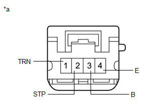
1. INSPECT REAR COMBINATION LIGHT ASSEMBLY LH
| (a) Apply battery voltage to the connector and check the light illumination condition. OK:
If the result is not as specified, replace the rear combination light assembly LH. |
|
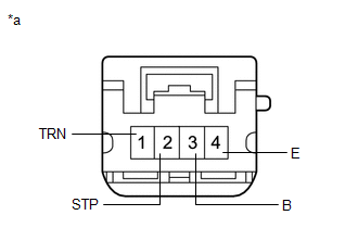
2. INSPECT REAR COMBINATION LIGHT ASSEMBLY RH
| (a) Apply battery voltage to the connector and check the light illumination condition. OK:
If the result is not as specified, replace the rear combination light assembly RH. |
|
READ NEXT:
 Reassembly
REASSEMBLY CAUTION / NOTICE / HINT HINT:
Use the same procedure for the RH and LH sides.
The procedure listed below is for the LH side.
PROCEDURE 1. INSTALL REAR COMBINATION LIGHT SOCKET AND W
Installation
INSTALLATION CAUTION / NOTICE / HINT HINT:
Use the same procedure for the RH and LH sides.
The procedure described below is for the LH side.
PROCEDURE 1. INSTALL REAR COMBINATION LIGHT ASSEMBL
SEE MORE:
Fuel information
You must only use unleaded gasoline
in your vehicle.
Select octane rating 87 (Research
Octane Number 91) or higher. Use
of unleaded gasoline with an octane
rating lower than 87 may result in
engine knocking. Persistent knocking
can lead to engine damage.
At minimum, the gasoline you use
s
On-vehicle Inspection
ON-VEHICLE INSPECTION PROCEDURE 1. INSPECT HOOD SUB-ASSEMBLY (a) Check that the clearance measurements of areas A to E are within the standard ranges. Standard Clearance: Area Specified Condition Area Specified Condition A 2.45 to 6.45 mm (0.0965 to 0.2539 in.) B 3.7 to 6.7 mm (
