Lexus NX: Components
COMPONENTS
ILLUSTRATION
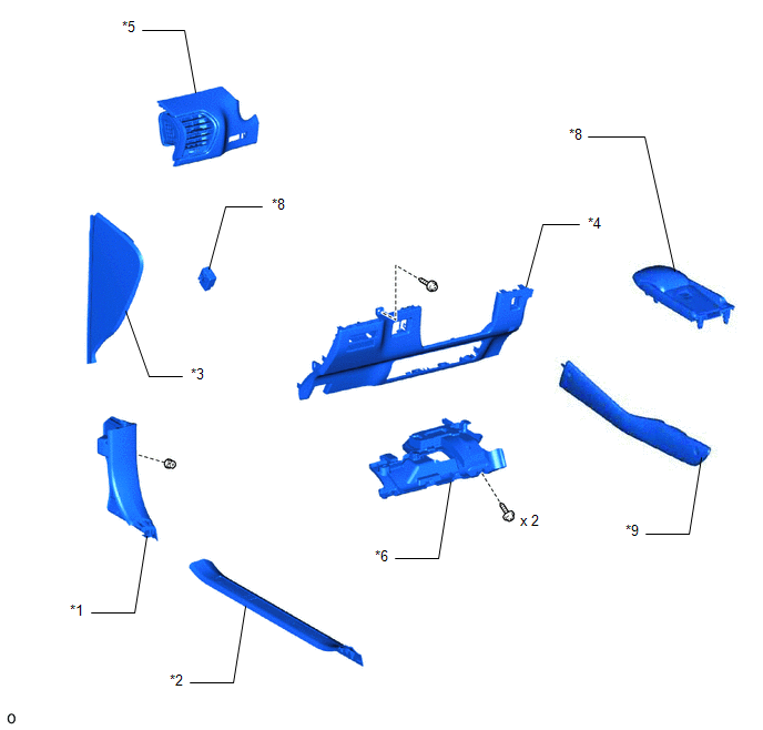
| *1 | COWL SIDE TRIM BOARD LH | *2 | DOOR SCUFF PLATE ASSEMBLY LH |
| *3 | INSTRUMENT SIDE PANEL LH | *4 | LOWER NO. 1 INSTRUMENT PANEL FINISH PANEL |
| *5 | NO. 1 INSTRUMENT PANEL SAFETY PAD SUB-ASSEMBLY | *6 | NO. 1 INSTRUMENT PANEL UNDER COVER SUB-ASSEMBLY |
| *7 | REAR CONSOLE ARMREST ASSEMBLY | *8 | STOP LIGHT CONTROL ECU ASSEMBLY |
| *9 | UPPER NO. 2 CONSOLE PANEL GARNISH | - | - |
READ NEXT:
 On-vehicle Inspection
ON-VEHICLE INSPECTION PROCEDURE 1. INSPECT STOP LIGHT CONTROL ECU ASSEMBLY (a) Disconnect the stop light control ECU assembly connector. *a Front view of wire harness connector (to S
Removal
REMOVAL PROCEDURE 1. REMOVE DOOR SCUFF PLATE ASSEMBLY LH Click here 2. REMOVE COWL SIDE TRIM BOARD LH Click here 3. REMOVE INSTRUMENT SIDE PANEL LH Click here 4. REMOVE NO. 1 INSTRUMENT
Installation
INSTALLATION PROCEDURE 1. INSTALL STOP LIGHT CONTROL ECU ASSEMBLY (a) Attach the clamp to install the stop light control ECU assembly. (b) Connect the connector. 2. INSTALL LOWER NO. 1 INSTRUMENT PANE
SEE MORE:
Power Source Mode does not Change to ON (IG)
DESCRIPTION If the power switch is pressed with the electrical key transmitter sub-assembly in the cabin, the certification ECU (smart key ECU assembly) receives a signal and changes the power source mode. Related Data List and Active Test Items Problem Symptom Data List and Active Test Pow
Problem Symptoms Table
PROBLEM SYMPTOMS TABLE NOTICE: If the main body ECU (multiplex network body ECU) is replaced, refer to Registration. Click here HINT:
Use the table below to help determine the cause of problem symptoms. If multiple suspected areas are listed, the potential causes of the symptoms are listed in
© 2016-2026 Copyright www.lexunx.com
