Lexus NX: On-vehicle Inspection
ON-VEHICLE INSPECTION
PROCEDURE
1. INSPECT STOP LIGHT CONTROL ECU ASSEMBLY
| (a) Disconnect the stop light control ECU assembly connector. |
|
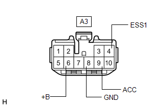
(b) Measure the voltage and resistance on the wire harness side connector according to the value (s) in the table below.
Standard Voltage:
| Tester Connection | Condition | Specified Condition |
|---|---|---|
| A3-4 (ESS1) - A3-8 (GND) | Power switch on (IG) | 11 to 14 V |
| A3-6 (+B) - A3-8 (GND) | Power switch off | 11 to 14 V |
| A3-9 (ACC) - A3-8 (GND) | Power switch on (IG) | 11 to 14 V |
Standard Resistance:
| Tester Connection | Condition | Specified Condition |
|---|---|---|
| A3-8 (GND) - Body ground | Always | Below 1 Ω |
If the result is not as specified, repair or replace the wire harness or connector.
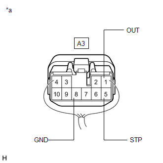
(c) Reconnect the stop light control ECU assembly connector.
| (d) Measure the voltage according to the value (s) in the table below. Standard Voltage:
If the result is not as specified, replace the stop light control ECU assembly. |
|
READ NEXT:
 Removal
REMOVAL PROCEDURE 1. REMOVE DOOR SCUFF PLATE ASSEMBLY LH Click here 2. REMOVE COWL SIDE TRIM BOARD LH Click here 3. REMOVE INSTRUMENT SIDE PANEL LH Click here 4. REMOVE NO. 1 INSTRUMENT
Installation
INSTALLATION PROCEDURE 1. INSTALL STOP LIGHT CONTROL ECU ASSEMBLY (a) Attach the clamp to install the stop light control ECU assembly. (b) Connect the connector. 2. INSTALL LOWER NO. 1 INSTRUMENT PANE
SEE MORE:
Removal
REMOVAL CAUTION / NOTICE / HINT NOTICE: While the auxiliary battery is connected, even if the power switch is off, the brake control system activates when the brake pedal is depressed or any door courtesy switch turns on. Therefore, when servicing the brake system components, do not operate the brak
System Voltage (P0560)
MONITOR DESCRIPTION The auxiliary battery supplies electricity to the ECM even when the power switch is off. This power allows the ECM to store data such as DTC history, freeze frame data and fuel trim values. If the auxiliary battery voltage falls below a minimum level, the memory is cleared and th
