Lexus NX: Components
COMPONENTS
ILLUSTRATION
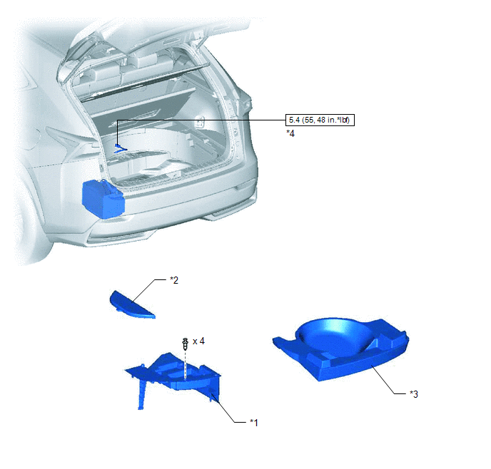
| *1 | DECK FLOOR BOX LH | *2 | NO. 3 DECK BOARD SUB-ASSEMBLY |
| *3 | REAR DECK FLOOR BOX | *4 | NEGATIVE AUXILIARY BATTERY TERMINAL |
.png) | N*m (kgf*cm, ft.*lbf): Specified torque | - | - |
ILLUSTRATION
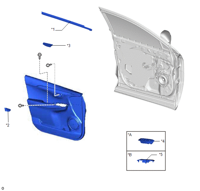
| *A | for Driver Side | *B | for Front Passenger Side |
| *1 | FRONT DOOR INNER GLASS WEATHERSTRIP LH | *2 | FRONT DOOR INSIDE HANDLE BEZEL PLUG LH |
| *3 | FRONT DOOR TRIM COVER LH | *4 | POWER WINDOW REGULATOR MASTER SWITCH ASSEMBLY WITH FRONT DOOR ARMREST BASE PANEL |
| *5 | POWER WINDOW REGULATOR SWITCH ASSEMBLY WITH FRONT DOOR ARMREST BASE PANEL | - | - |
ILLUSTRATION
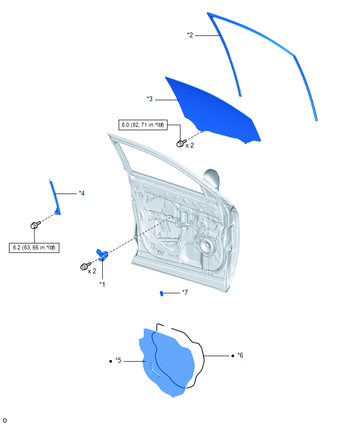
| *1 | FRONT DOOR ARMREST SET BRACKET LH | *2 | FRONT DOOR GLASS RUN LH |
| *3 | FRONT DOOR GLASS SUB-ASSEMBLY LH | *4 | FRONT DOOR REAR LOWER FRAME SUB-ASSEMBLY LH |
| *5 | FRONT DOOR SERVICE HOLE COVER LH | *6 | BUTYL TAPE |
| *7 | HOLE PLUG | - | - |
| | N*m (kgf*cm, ft.*lbf): Specified torque | ● | Non-reusable part |
ILLUSTRATION
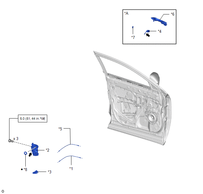
| *A | for Driver Side | - | - |
| *1 | FRONT DOOR INSIDE LOCKING CABLE ASSEMBLY LH | *2 | FRONT DOOR LOCK ASSEMBLY LH |
| *3 | FRONT DOOR LOCK COVER SUB-ASSEMBLY LH | *4 | FRONT DOOR LOCK CYLINDER ASSEMBLY LH |
| *5 | FRONT DOOR LOCK REMOTE CONTROL CABLE ASSEMBLY LH | *6 | FRONT DOOR OUTSIDE HANDLE ASSEMBLY LH |
| *7 | HOLE PLUG | *8 | DOOR LOCK WIRING HARNESS SEAL |
| | N*m (kgf*cm, ft.*lbf): Specified torque | ● | Non-reusable part |
.png) | MP grease | - | - |
READ NEXT:
 Removal
REMOVAL CAUTION / NOTICE / HINT HINT:
Use the same procedure for the RH and LH sides.
The procedure listed below is for the LH side.
PROCEDURE 1. PRECAUTION NOTICE: After turning the power swi
Inspection
INSPECTION PROCEDURE 1. INSPECT FRONT DOOR LOCK ASSEMBLY LH (a) Check the door lock motor operation. (1) Apply auxiliary battery voltage to the motor connector and check the operation of the door l
Installation
INSTALLATION CAUTION / NOTICE / HINT HINT:
Use the same procedure for the RH and LH sides.
The procedure listed below is for the LH side.
A bolt without a torque specification is shown in the s
SEE MORE:
Terminals Of Ecu
TERMINALS OF ECU CHECK STEREO COMPONENT EQUALIZER ASSEMBLY (a) Measure the voltage and resistance according to the value(s) in the table below. Terminal No. (Symbol) Wiring Color Terminal Description Condition Specified Condition I117-1 (GND) - Body ground W-B - Body ground Groun
P/W Master Switch Communication Stop (B1206)
DESCRIPTION This DTC is stored when LIN communication between the multiplex network master switch assembly and main body ECU (multiplex network body ECU) stops for 10 seconds or more. DTC No. Detection Item DTC Detection Condition Trouble Area B1206 P/W Master Switch Communication Sto
