Lexus NX: Removal
REMOVAL
CAUTION / NOTICE / HINT
HINT:
- Use the same procedure for the RH and LH sides.
- The procedure listed below is for the LH side.
PROCEDURE
1. PRECAUTION
NOTICE:
After turning the power switch off, waiting time may be required before disconnecting the cable from the negative (-) auxiliary battery terminal.
Click here .gif)
2. REMOVE NO. 3 DECK BOARD SUB-ASSEMBLY
Click here
3. REMOVE REAR DECK FLOOR BOX
Click here
4. REMOVE DECK FLOOR BOX LH
Click here
5. DISCONNECT CABLE FROM NEGATIVE AUXILIARY BATTERY TERMINAL
CAUTION:
Wait at least 90 seconds after disconnecting the cable from the negative (-) battery terminal to disable the SRS system.
6. REMOVE FRONT DOOR TRIM COVER LH
Click here
7. REMOVE FRONT DOOR INSIDE HANDLE BEZEL PLUG LH
Click here
8. REMOVE POWER WINDOW REGULATOR MASTER SWITCH ASSEMBLY WITH FRONT DOOR ARMREST BASE PANEL (for Driver Side)
Click here
9. REMOVE POWER WINDOW REGULATOR SWITCH ASSEMBLY WITH FRONT DOOR ARMREST BASE PANEL (for Front Passenger Side)
Click here
10. REMOVE FRONT DOOR TRIM BOARD SUB-ASSEMBLY LH
Click here
11. REMOVE FRONT DOOR INNER GLASS WEATHERSTRIP LH
Click here
12. REMOVE FRONT DOOR ARMREST SET BRACKET LH
Click here
13. REMOVE FRONT DOOR SERVICE HOLE COVER LH
Click here
14. REMOVE FRONT DOOR GLASS RUN LH
Click here
15. REMOVE FRONT DOOR GLASS SUB-ASSEMBLY LH
Click here
16. REMOVE FRONT DOOR REAR LOWER FRAME SUB-ASSEMBLY LH
Click here
17. REMOVE FRONT DOOR OUTSIDE HANDLE ASSEMBLY LH
Click here
18. REMOVE FRONT DOOR LOCK CYLINDER ASSEMBLY LH (for Driver Side)
Click here
19. REMOVE FRONT DOOR LOCK ASSEMBLY LH
(a) Disconnect the connector.
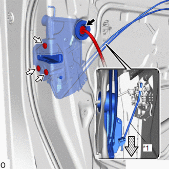
| *1 | Front Door Lock Open Rod LH |
 | Downward |
(1) Using a T30 "TORX" socket wrench, remove the 3 screws.
(2) Slide the front door lock assembly LH downward, and remove the front door lock assembly LH and cables as a unit.
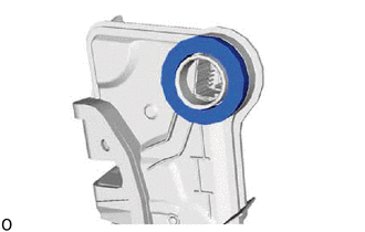
20. REMOVE DOOR LOCK WIRING HARNESS SEAL
| (a) Remove the door lock wiring harness seal from the front door lock assembly LH. |
|
21. REMOVE FRONT DOOR LOCK COVER SUB-ASSEMBLY LH
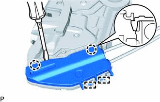
(a) Using a screwdriver, detach the 2 claws.
(b) Detach the 2 guides and remove the front door lock cover sub-assembly LH from the front door lock assembly LH.
22. REMOVE FRONT DOOR LOCK REMOTE CONTROL CABLE ASSEMBLY LH
| (a) Detach the clamp and remove the front door lock remote control cable assembly LH from the front door lock assembly LH. |
|
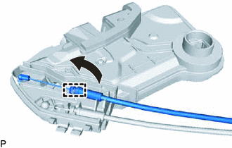
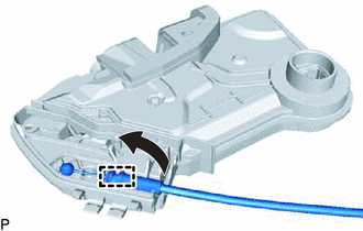
23. REMOVE FRONT DOOR INSIDE LOCKING CABLE ASSEMBLY LH
| (a) Detach the clamp and remove the front door lock remote control cable assembly LH from the front door lock assembly LH. |
|
READ NEXT:
 Inspection
INSPECTION PROCEDURE 1. INSPECT FRONT DOOR LOCK ASSEMBLY LH (a) Check the door lock motor operation. (1) Apply auxiliary battery voltage to the motor connector and check the operation of the door l
Installation
INSTALLATION CAUTION / NOTICE / HINT HINT:
Use the same procedure for the RH and LH sides.
The procedure listed below is for the LH side.
A bolt without a torque specification is shown in the s
SEE MORE:
Installation
INSTALLATION PROCEDURE 1. INSTALL STEERING WHEEL HEATER CONTROL ASSEMBLY (a) Connect the connector to the steering wheel heater control assembly. (b) Install the steering wheel heater control assembly to the lower steering wheel boss cover with the 2 screws. NOTICE: If the heater thermistor comes of
LED Headlight LH Circuit Malfunction (B2430,B2431)
DESCRIPTION The illumination of the low beam headlights is controlled by the main body ECU (multiplex network body ECU). When the headlights are turned on, the main body ECU (multiplex network body ECU) receives a signal from the headlight assembly and detects the illumination condition of the low b
