Lexus NX: Components
COMPONENTS
ILLUSTRATION
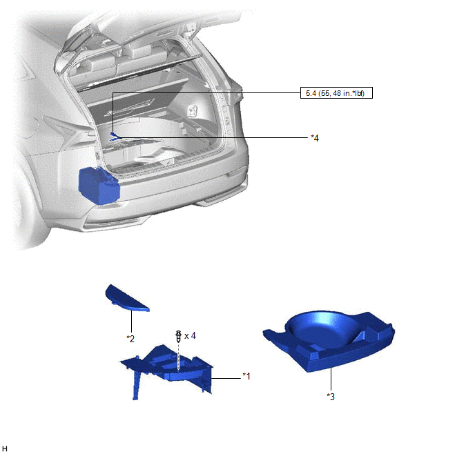
| *1 | DECK FLOOR BOX LH | *2 | NO. 3 DECK BOARD SUB-ASSEMBLY |
| *3 | REAR DECK FLOOR BOX | *4 | NEGATIVE AUXILIARY BATTERY TERMINAL |
.png) | N*m (kgf*cm, ft.*lbf): Specified torque | - | - |
ILLUSTRATION
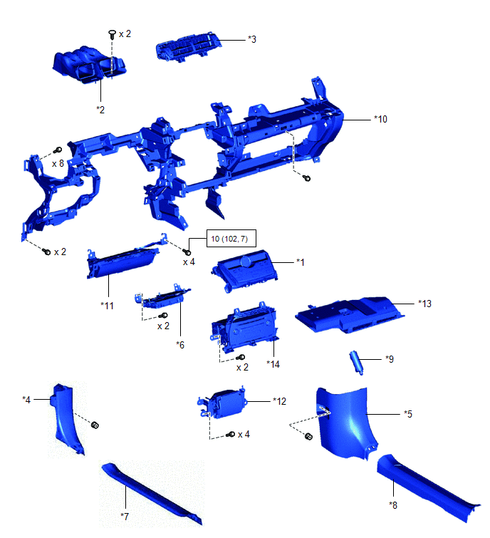
| *1 | AIR CONDITIONING CONTROL ASSEMBLY | *2 | CENTER HEATER TO REGISTER DUCT |
| *3 | CENTER INSTRUMENT PANEL REGISTER ASSEMBLY | *4 | COWL SIDE TRIM BOARD LH |
| *5 | COWL SIDE TRIM BOARD RH | *6 | DCM (TELEMATICS TRANSCEIVER) WITH BRACKET |
| *7 | DOOR SCUFF PLATE ASSEMBLY LH | *8 | DOOR SCUFF PLATE ASSEMBLY RH |
| *9 | GLOVE COMPARTMENT DOOR STOPPER SUB-ASSEMBLY | *10 | LOWER INSTRUMENT PANEL SUB-ASSEMBLY |
| *11 | LOWER NO. 1 INSTRUMENT PANEL AIRBAG ASSEMBLY | *12 | NO. 1 SPEAKER ASSEMBLY WITH BOX |
| *13 | NO. 2 INSTRUMENT PANEL UNDER COVER SUB-ASSEMBLY | *14 | RADIO RECEIVER ASSEMBLY WITH BRACKET |
| | N*m (kgf*cm, ft.*lbf): Specified torque | - | - |
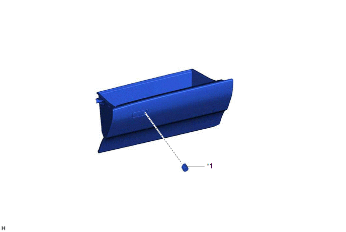
ILLUSTRATION
| *1 | GLOVE BOX LIGHT ASSEMBLY | *2 | GLOVE COMPARTMENT DOOR CHECK CUSHION |
ILLUSTRATION
| *1 | GLOVE COMPARTMENT DOOR LOCK CYLINDER ASSEMBLY | - | - |
READ NEXT:
 Removal
REMOVAL PROCEDURE 1. TABLE OF BOLT, SCREW AND CLIP HINT: All bolts, screws, and clips relevant to installing and removing the instrument panel are shown along with their alphabet code in the table bel
Disassembly
DISASSEMBLY PROCEDURE 1. REMOVE GLOVE COMPARTMENT DOOR CHECK CUSHION HINT: Use the same procedure for both glove compartment door check cushions. (a) Using a screwdriver, detach the 3 claws and rem
Reassembly
REASSEMBLY PROCEDURE 1. INSTALL GLOVE COMPARTMENT DOOR LOCK CYLINDER ASSEMBLY (a) With the cylinder lock pressed, insert the glove compartment door lock cylinder assembly into the glove compartment do
SEE MORE:
Operation Check
OPERATION CHECK CHECK WINDOW DEFOGGER SYSTEM (a) Turn the power switch on (IG). (b) Check that the rear window defogger becomes warm by operating the rear window defogger switch of the air conditioning control assembly. (c) When the vehicle is stopped, confirm that the rear window defogger stops aft
Dtc Check / Clear
DTC CHECK / CLEAR CHECK FOR DTC (a) Connect the Techstream to the DLC3. (b) Turn the power switch on (IG). (c) Turn the Techstream on. (d) Enter the following menus: Body Electrical / Main body / Trouble Codes. Body Electrical > Main Body > Trouble Codes (e) Body Electrical / Front Recognition
