Lexus NX: Customize Parameters
CUSTOMIZE PARAMETERS
CUSTOMIZE LIGHTING SYSTEM (EXT)
NOTICE:
- When the customer requests a change in a function, first make sure that the function can be customized.
- Record the current settings before customizing.
HINT:
The following items can be customized.
(a) Customizing with the Techstream.
(1) Connect the Techstream to the DLC3.
(2) Turn the power switch on (IG).
(3) Turn the Techstream on.
(4) Enter the following menus: Utility / Customize / (desired system).
(5) Select the setting by referring to the table below.
Light Control| Tester Display | Description | Default | Setting | ECU |
|---|---|---|---|---|
| Disp Ex ON Sen | Sets the display light (meter, audio, etc.) dim starting level.*A | NORMAL | 000:NORMAL,001:DARK2,010:DARK1,011:LIGHT1,100:LIGHT2 | Main body ECU (Multiplex network body ECU) |
| Disp Ex OFF Sen | Sets the display light (meter, audio, etc.) dim return level.*B | NORMAL | 000:NORMAL,001:DARK2,010:DARK1,011:LIGHT1,100:LIGHT2 | Main body ECU (Multiplex network body ECU) |
| Light Auto OFF Delay | Keep the headlights on for a certain period of time after turning the power switch off and closing all doors with the low beam headlights on. | 30 s | 00:OFF,01:30 s,10:60 s,11:90 s | Main body ECU (Multiplex network body ECU) |
| Sensitivity | Adjusts the ambient light sensitivity of the automatic light control system.*C | Normal | 000:Normal,001:Dark2,010:Dark1,011:Light1,100:Light2 | Main body ECU (Multiplex network body ECU) |
| DRL Function | ON/OFF of the DRL function | ON | 0:OFF,1:ON | Main body ECU (Multiplex network body ECU) |
| Light up Clearance Lights at Door Unlock Function | Turns on the clearance lights and the taillights for 15 seconds when the doors are unlocked by the smart key or the wireless key. | ON | 0:OFF,1:ON | Main body ECU (Multiplex network body ECU) |
| Tester Display | Description | Default | Setting | ECU |
|---|---|---|---|---|
| Lane Change Flashing Times Setting | Function to change the lane change flashing times. | 3 | 000:OFF,001:3,010:4,011:5,100:6,101:7 | Combination meter assembly |
HINT:
The sensitivity adjustment may be difficult to confirm. Check by driving the customer's vehicle.
*A
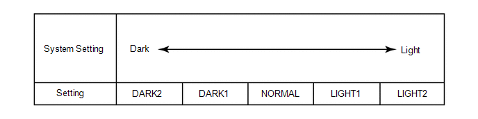
HINT:
When the setting is closer to the "Light" side, the system dims the indicator lights even when the surrounding area is relatively bright. When the setting is closer to the "Dark" side, the system waits until the surrounding area is darker before dimming the indicator lights.
*B
HINT:
When the setting is closer to the "Dark" side, the system cancels the dimming of the indicator lights even when the surrounding area is relatively dark. When the setting is closer to the "Light" side, the system waits until the surrounding area is brighter before canceling the dimming of the indicator lights.
*C
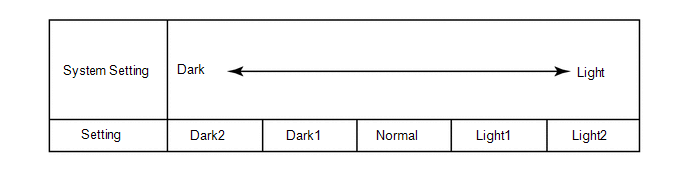
HINT:
When the setting is closer to the "Light" side, the system turns the lights on even when the surrounding area is relatively bright. When the setting is closer to the "Dark" side, the system waits until the surrounding area is darker before turning on the lights.
(b) Customizing with Multi-display.
(1) Turn the power switch on (IG).
(2) Enter the following menus: Setup / Vehicle Customization / Lights Settings.
(3) Select the setting by referring to the table below.
Warning| Display | Default | Content | Setting | Relevant ECU |
|---|---|---|---|---|
| Light Sensor Sensitivity | 0 (middle bar) | Adjusts the ambient light sensitivity of the automatic light control system.*A | -2, -1, 0, +1 or +2 | Main body ECU (Multiplex network body ECU) |
HINT:
The sensitivity adjustment may be difficult to confirm. Check by driving the customer's vehicle.
*A
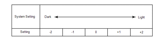
HINT:
When the setting is closer to the "Light" side, the system turns the lights on even when the surrounding area is relatively bright. When the setting is closer to the "Dark" side, the system waits until the surrounding area is darker before turning on the lights.
READ NEXT:
 Problem Symptoms Table
PROBLEM SYMPTOMS TABLE NOTICE:
Recognition code registration is necessary when replacing the main body ECU (multiplex network body ECU).
If the main body ECU (multiplex network body ECU) is repla
Terminals Of Ecu
TERMINALS OF ECU CHECK INSTRUMENT PANEL JUNCTION BLOCK ASSEMBLY, MAIN BODY ECU (MULTIPLEX NETWORK BODY ECU) (a) Remove the main body ECU (multiplex network body ECU) from the instrument panel junction
Dtc Check / Clear
DTC CHECK / CLEAR CHECK FOR DTC (a) Connect the Techstream to the DLC3. (b) Turn the power switch on (IG). (c) Turn the Techstream on. (d) Enter the following menus: Body Electrical / Main body / Trou
SEE MORE:
Throttle / Pedal Position Sensor / Switch "D" Circuit (P2120-152,...,P2138-154)
DESCRIPTION The accelerator pedal position sensor is mounted on the accelerator pedal to detect how much the pedal is depressed. This is a non-contact sensor with Hall elements. There are 2 outputs from the sensor. One is used to detect the accelerator pedal position and the other is used as a confi
Problem Symptoms Table
PROBLEM SYMPTOMS TABLE NOTICE:
If the auxiliary battery voltage is low, the climate control seat system may not operate. When "High Power Consumption Partial Limit On AC/Heater Operation." is displayed on the multi-information display in the combination meter assembly, inspect the auxiliary batte
