- Accel Pedal Pos #1
- Accel Pedal Pos #2
Lexus NX: Throttle / Pedal Position Sensor / Switch "D" Circuit (P2120-152,...,P2138-154)
Lexus NX Service Manual / Engine & Hybrid System / 2ar-fxe (hybrid / Battery Control) / Hybrid Control System / Throttle / Pedal Position Sensor / Switch "D" Circuit (P2120-152,...,P2138-154)
DESCRIPTION
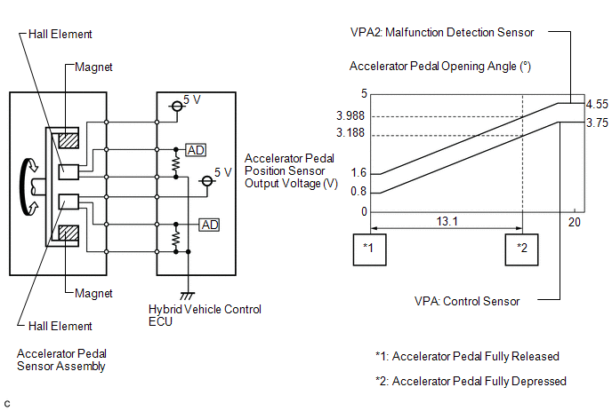
The accelerator pedal position sensor is mounted on the accelerator pedal to detect how much the pedal is depressed. This is a non-contact sensor with Hall elements. There are 2 outputs from the sensor. One is used to detect the accelerator pedal position and the other is used as a confirmation to allow the detection of a malfunction in the sensor itself. Voltage is output from the accelerator pedal position sensor to terminals VPA and VPA2 of the hybrid vehicle control ECU. This voltage varies from 0 to 5 V in accordance with the accelerator pedal position. Terminal VPA2 is primarily used to detect a malfunction in the sensor itself. The hybrid vehicle control ECU determines the current accelerator pedal position and controls the hybrid control system based on signals received by terminals VPA and VPA2.
| DTC No. | Detection Item | DTC Detection Condition | Trouble Area | MIL | Warning Indicate |
|---|---|---|---|---|---|
| P2120-152 | Throttle / Pedal Position Sensor / Switch "D" Circuit | Main sensor circuit wiring malfunction or level is not stable: Main sensor voltage is 0.4 V or less or 4.8 V or more for a certain period of time. (Both of the following conditions are met: The main sensor voltage is 0.4 V or less for a certain period of time and 4.8 V or more for a certain period of time.) (1 trip detection logic) |
| Comes on | Master Warning Light: Comes on |
| P2121-106 | Throttle / Pedal Position Sensor / Switch "D" Circuit Range / Performance | Internal malfunction in the main sensor: Main sensor output changes rapidly (detected when there are no circuit malfunctions such as an open or short). (1 trip detection logic) |
| Comes on | Master Warning Light: Comes on |
| P2122-104 | Throttle / Pedal Position Sensor / Switch "D" Circuit Low Input | Open or short to ground in the main sensor circuit: The main sensor voltage is 0.4 V or less for 0.5 seconds. (1 trip detection logic) |
| Comes on | Master Warning Light: Comes on |
| P2123-105 | Throttle / Pedal Position Sensor / Switch "D" Circuit High Input | Short to +B in the main sensor circuit: The main sensor voltage is 4.8 V or more for 2 seconds. (1 trip detection logic) |
| Comes on | Master Warning Light: Comes on |
| P2125-153 | Throttle / Pedal Position Sensor / Switch "E" Circuit | Sub sensor circuit wiring malfunction or level is not stable: When the main sensor circuit is normal, the sub sensor voltage is 1.2 V or less or 4.8 V or more for a certain period of time. (Both of the following conditions are met: Sub sensor voltage is 1.2 V or less for a certain period of time, and the main sensor is normal and sub sensor voltage is 4.8 V or more for a certain period of time.) (1 trip detection logic) |
| Comes on | Master Warning Light: Comes on |
| P2126-109 | Throttle / Pedal Position Sensor / Switch "E" Circuit Range / Performance | Internal malfunction of the sub sensor: Sub sensor output changes rapidly (detected when there are no circuit malfunctions such as an open or short). (1 trip detection logic) |
| Comes on | Master Warning Light: Comes on |
| P2127-107 | Throttle / Pedal Position Sensor / Switch "E" Circuit Low Input | Open or short to ground in the sub sensor circuit: The sub sensor voltage is 1.2 V or less for 0.5 seconds. (1 trip detection logic) |
| Comes on | Master Warning Light: Comes on |
| P2128-108 | Throttle / Pedal Position Sensor / Switch "E" Circuit High Input | Short to +B in the sub sensor circuit: Main sensor is normal and sub sensor voltage is 4.8 V or more for 2 seconds. (1 trip detection logic) |
| Comes on | Master Warning Light: Comes on |
| P2138-110 | Throttle / Pedal Position Sensor / Switch "D" / "E" Voltage Correlation | Difference between the main sensor value and sub sensor value is large. (1 trip detection logic) |
| Comes on | Master Warning Light: Comes on |
| P2138-154 | Throttle / Pedal Position Sensor / Switch "D" / "E" Voltage Correlation | Main or sub sensor circuit wiring malfunction: The difference in voltage between the main sensor and sub sensor is 0.02 V or less, or a low output malfunction continues in both the main and sub sensors for a certain period of time. (1 trip detection logic) |
| Comes on | Master Warning Light: Comes on |
| DTC No. | Data List |
|---|---|
| P2120-152 | |
| P2121-106 | |
| P2122-104 | |
| P2123-105 | |
| P2125-153 | |
| P2126-109 | |
| P2127-107 | |
| P2128-108 | |
| P2138-110 | |
| P2138-154 |
MONITOR DESCRIPTION
The hybrid vehicle control ECU calculates the differences of the voltage of main accelerator sensor and sub accelerator sensor. If the differences exceed prescribed values, the hybrid vehicle control ECU determines that there is a malfunction in the accelerator sensor circuit. If the hybrid vehicle control ECU detects this malfunction, it will illuminate the MIL and store a DTC.
MONITOR STRATEGY
| Related DTCs | P2123 (INF 105): Accelerator Pedal Position Sensor (APP Sensor) Sensor 1 Range Check (High voltage) P2122 (INF 104): Accelerator Pedal Position Sensor (APP Sensor) Sensor 1 Range Check (Low voltage) P2121 (INF 106): Throttle/Pedal Position Sensor/Switch "D" Voltage Out of Range P2120 (INF 152): Accelerator Pedal Position Sensor (APP Sensor) Sensor 1 Range Check (Chattering) P2128 (INF 108): Accelerator Pedal Position Sensor (APP Sensor) Sensor 2 Range Check (High voltage) P2127 (INF 107): Accelerator Pedal Position Sensor (APP Sensor) Sensor 2 Range Check (Low voltage) P2126 (INF 109): Throttle/Pedal Position Sensor/Switch "E" Voltage Out of Range P2125 (INF 153): Accelerator Pedal Position Sensor (APP Sensor) Sensor 2 Range Check (Chattering) P2138 (INF 110): Throttle/Pedal Position Sensor/Switch "D"/"E" Voltage Correlation P2138 (INF 154): Accelerator Pedal Position Sensor (APP Sensor) Correlation |
| Required sensors/components | Throttle/Pedal Position Sensor/Switch |
| Frequency of operation | Continuous |
| Duration | TMC's intellectual property |
| MIL operation | Immediately / 1 driving cycle |
| Sequence of operation | None |
TYPICAL ENABLING CONDITIONS
| The monitor will run whenever the following DTCs are not stored | TMC's intellectual property |
| Other conditions belong to TMC's intellectual property | - |
TYPICAL MALFUNCTION THRESHOLDS
| TMC's intellectual property | - |
COMPONENT OPERATING RANGE
| Hybrid vehicle control ECU | DTC P2123 (INF 105) is not detected DTC P2122 (INF 104) is not detected DTC P2121 (INF 106) is not detected DTC P2120 (INF 152) is not detected DTC P2128 (INF 108) is not detected DTC P2127 (INF 107) is not detected DTC P2126 (INF 109) is not detected DTC P2125 (INF 153) is not detected DTC P2138 (INF 110) is not detected DTC P2138 (INF 154) is not detected |
CONFIRMATION DRIVING PATTERN
HINT:
-
After repair has been completed, clear the DTC and then check that the vehicle has returned to normal by performing the following All Readiness check procedure.
Click here
.gif)
-
When clearing the permanent DTCs, refer to the "CLEAR PERMANENT DTC" procedure.
Click here
- Connect the Techstream to the DLC3.
- Turn the power switch on (IG) and turn the Techstream on.
- Clear the DTCs (even if no DTCs are stored, perform the clear DTC procedure).
- Turn the power switch off and wait for 2 minutes or more.
- Turn the power switch on (IG) and turn the Techstream on.
- Wait for approximately 10 seconds with the power switch on (READY) and shift lever in P, then fully depress and release the accelerator pedal several times.
- Enter the following menus: Powertrain / Hybrid Control / Trouble Codes.
-
Read the current DTCs.
HINT:
- If a current DTC is output, the system is malfunctioning.
- If current DTCs are not output, check for permanent DTCs.
- Check that the permanent DTCs are cleared.
- If the permanent DTCs are not cleared, perform the universal trip, and then check for permanent DTCs again.
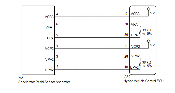
WIRING DIAGRAM
CAUTION / NOTICE / HINT
HINT:
After the repair, clear the DTCs and perform the following procedure to check that DTCs are not output.
- Wait for approximately 10 seconds with the power switch on (READY) and the shift lever in P, then fully depress and release the accelerator pedal several times.
PROCEDURE
| 1. | READ VALUE USING TECHSTREAM (ACCEL PEDAL POS #1, ACCEL PEDAL POS #2) |
(a) Connect the Techstream to the DLC3.
(b) Turn the power switch on (IG).
(c) Enter the following menus: Powertrain / Hybrid Control / Data List / Accel Pedal Pos #1, Accel Pedal Pos #2.
Powertrain > Hybrid Control > Data List| Tester Display |
|---|
| Accel Pedal Pos #1 |
| Accel Pedal Pos #2 |
(d) Read the Data List.
Standard:
| Tester Display | Accelerator Pedal Condition | Specified Condition |
|---|---|---|
| Accel Pedal Pos #1 | Not depressed | 10 to 22% |
| Fully depressed | 52 to 90% | |
| Not depressed → Fully depressed → Not depressed (Accelerator pedal should be operated slowly) | Value changes progressively | |
| Accel Pedal Pos #2 | Not depressed | 24 to 40% |
| Fully depressed | 68 to 99% | |
| Not depressed → Fully depressed → Not depressed (Accelerator pedal should be operated slowly) | Value changes progressively |
(e) Turn the power switch off.
| OK | .gif) | CHECK FOR INTERMITTENT PROBLEMS |
|
.gif)
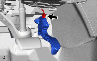
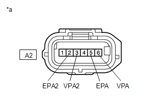
| 2. | CHECK CONNECTOR CONNECTION CONDITION (ACCELERATOR PEDAL SENSOR ASSEMBLY CONNECTOR) |
| (a) Check the connector connections and contact pressure of the relevant terminals for the accelerator pedal sensor assembly connector. Click here OK: The connectors are connected securely and there are no contact pressure problems. |
|
| NG | | CONNECT SECURELY |
|
| 3. | CHECK CONNECTOR CONNECTION CONDITION (HYBRID VEHICLE CONTROL ECU CONNECTOR) |
Click here
| NG | | CONNECT SECURELY |
|
| 4. | CHECK HYBRID VEHICLE CONTROL ECU (CHECK VOLTAGE) |
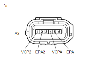
(a) Disconnect the A2 accelerator pedal sensor assembly connector.
(b) Turn the power switch on (IG).
| (c) Measure the voltage according to the value(s) in the table below. Standard Voltage:
|
|
(d) Turn the power switch off.
(e) Reconnect the A2 accelerator pedal sensor assembly connector.
| NG | | GO TO STEP 6 |
|
| 5. | CHECK HYBRID VEHICLE CONTROL ECU (CHECK RESISTANCE) |
(a) Disconnect the A2 accelerator pedal sensor assembly connector.
| (b) Measure the resistance according to the value(s) in the table below. Standard Resistance:
|
|
(c) Reconnect the A2 accelerator pedal sensor assembly connector.
| OK | | REPLACE ACCELERATOR PEDAL(W/SENSOR) ROD ASSEMBLY |
| NG | | GO TO STEP 7 |
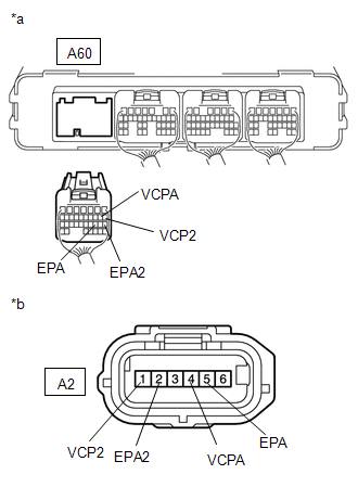
| 6. | CHECK HARNESS AND CONNECTOR (HYBRID VEHICLE CONTROL ECU - ACCELERATOR PEDAL SENSOR ASSEMBLY) |
(a) Disconnect the A60 hybrid vehicle control ECU connector.
(b) Disconnect the A2 accelerator pedal sensor assembly connector.
(c) Turn the power switch on (IG).
| (d) Measure the voltage according to the value(s) in the table below. Standard Voltage:
NOTICE: Turning the power switch on (IG) with the hybrid vehicle control ECU connector disconnected causes other DTCs to be stored. Clear the DTCs after performing this inspection. |
|
(e) Turn the power switch off.
(f) Measure the resistance according to the value(s) in the table below.
Standard Resistance (Check for Open):
| Tester Connection | Condition | Specified Condition |
|---|---|---|
| A60-9 (VCPA) - A2-4 (VCPA) | Power switch off | Below 1 Ω |
| A60-20 (EPA) - A2-5 (EPA) | Power switch off | Below 1 Ω |
| A60-8 (VCP2) - A2-1 (VCP2) | Power switch off | Below 1 Ω |
| A60-18 (EPA2) - A2-2 (EPA2) | Power switch off | Below 1 Ω |
Standard Resistance (Check for Short):
| Tester Connection | Condition | Specified Condition |
|---|---|---|
| A60-9 (VCPA) or A2-4 (VCPA) - Body ground and other terminals | Power switch off | 10 kΩ or higher |
| A60-20 (EPA) or A2-5 (EPA) - Body ground and other terminals | Power switch off | 10 kΩ or higher |
| A60-8 (VCP2) or A2-1 (VCP2) - Body ground and other terminals | Power switch off | 10 kΩ or higher |
| A60-18 (EPA2) or A2-2 (EPA2) - Body ground and other terminals | Power switch off | 10 kΩ or higher |
(g) Reconnect the A2 accelerator pedal sensor assembly connector.
(h) Reconnect the A60 hybrid vehicle control ECU connector.
| OK | | REPLACE HYBRID VEHICLE CONTROL ECU |
| NG | | REPAIR OR REPLACE HARNESS OR CONNECTOR |
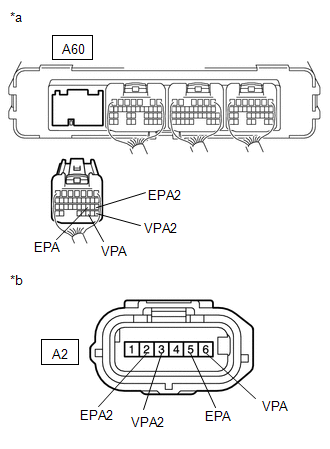
| 7. | CHECK HARNESS AND CONNECTOR (HYBRID VEHICLE CONTROL ECU - ACCELERATOR PEDAL SENSOR ASSEMBLY) |
(a) Disconnect the A60 hybrid vehicle control ECU connector.
(b) Disconnect the A2 accelerator pedal sensor assembly connector.
(c) Turn the power switch on (IG).
| (d) Measure the voltage according to the value(s) in the table below. Standard Voltage:
NOTICE: Turning the power switch on (IG) with the hybrid vehicle control ECU connector disconnected causes other DTCs to be stored. Clear the DTCs after performing this inspection. |
|
(e) Turn the power switch off.
(f) Measure the resistance according to the value(s) in the table below.
Standard Resistance (Check for Open):
| Tester Connection | Condition | Specified Condition |
|---|---|---|
| A60-30 (VPA) - A2-6 (VPA) | Power switch off | Below 1 Ω |
| A60-20 (EPA) - A2-5 (EPA) | Power switch off | Below 1 Ω |
| A60-28 (VPA2) - A2-3 (VPA2) | Power switch off | Below 1 Ω |
| A60-18 (EPA2) - A2-2 (EPA2) | Power switch off | Below 1 Ω |
Standard Resistance (Check for Short):
| Tester Connection | Condition | Specified Condition |
|---|---|---|
| A60-30 (VPA) or A2-6 (VPA) - Body ground and other terminals | Power switch off | 10 kΩ or higher |
| A60-20 (EPA) or A2-5 (EPA) - Body ground and other terminals | Power switch off | 10 kΩ or higher |
| A60-28 (VPA2) or A2-3 (VPA2) - Body ground and other terminals | Power switch off | 10 kΩ or higher |
| A60-18 (EPA2) or A2-2 (EPA2) - Body ground and other terminals | Power switch off | 10 kΩ or higher |
(g) Reconnect the A2 accelerator pedal sensor assembly connector.
(h) Reconnect the A60 hybrid vehicle control ECU connector.
| OK | | REPLACE HYBRID VEHICLE CONTROL ECU |
| NG | | REPAIR OR REPLACE HARNESS OR CONNECTOR |
READ NEXT:
 Barometric Pressure Sensor "A" Circuit Low (P2228-268,P2229-269)
DESCRIPTION Refer to the description for DTC P0069-273. Click here DTC No. Detection Item DTC Detection Condition Trouble Area MIL Warning Indicate P2228-268 Barometric Pressure
Ignition Switch Run Position Circuit High (P2532-772)
DESCRIPTION The hybrid vehicle control ECU monitors the IGSW signals sent from the smart key ECU assembly (certification ECU) and detects a malfunction. HINT: If DTC P2532-772 is stored, the vehicle w
Battery Control System (P3000-388)
DESCRIPTION The hybrid vehicle control ECU alerts the driver and performs fail-safe control based on error signals received from the battery voltage sensor. This DTC is stored when the SOC (state of c
SEE MORE:
Removal
REMOVAL PROCEDURE 1. REMOVE LOWER INSTRUMENT PANEL Click here 2. REMOVE NO. 1 AIR DUCT Click here 3. REMOVE QUICK HEATER ASSEMBLY (a) Detach the clamp and disconnect the 2 connectors. (b) Remove the screw and quick heater assembly.
IG Signal Circuit
DESCRIPTION This circuit detects whether the power switch is on (IG) or off, and sends this information to the main body ECU (multiplex network body ECU). WIRING DIAGRAM CAUTION / NOTICE / HINT NOTICE:
Inspect the fuses for circuits related to this system before performing the following procedur
© 2016-2026 Copyright www.lexunx.com
