Lexus NX: Daytime Running Light Relay Circuit
DESCRIPTION
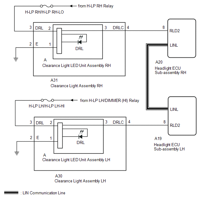
The illumination of the daytime running light (clearance light assembly) or clearance light is controlled by the headlight ECU sub-assembly.
WIRING DIAGRAM
CAUTION / NOTICE / HINT
NOTICE:
Inspect the fuses for circuits related to this system before performing the following inspection procedure.
PROCEDURE
| 1. | PERFORM ACTIVE TEST USING TECHSTREAM (DAYTIME RUNNING LIGHT) |
(a) Using the Techstream, perform the Active Test.
Click here .gif)
| Tester Display | Measurement Item | Control Range | Diagnostic Note |
|---|---|---|---|
| Clearance Light | Illuminates cornering lights | OFF or ON | - |
| Daytime Running Light | Illuminates daytime running lights | OFF or ON | - |
| Tester Display |
|---|
| Clearance Light |
| Tester Display |
|---|
| Daytime Running Light |
| Result | Proceed to |
|---|---|
| The Active Test is performed normally | A |
| The Active Test is not performed normally for the right side light only | B |
| The Active Test is not performed normally for the left side light only | C |
| A | .gif) | PROCEED TO NEXT SUSPECTED AREA SHOWN IN PROBLEM SYMPTOMS TABLE |
| C | | GO TO STEP 5 |
|
.gif)
| 2. | CHECK HARNESS AND CONNECTOR (CLEARANCE LIGHT ASSEMBLY RH - BATTERY AND BODY GROUND) |
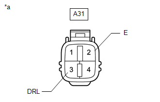
| (a) Disconnect the clearance light assembly RH connector. |
|
(b) Measure the voltage according to the value(s) in the table below.
Standard Voltage:
| Tester Connection | Switch Condition | Specified Condition |
|---|---|---|
| A31-3 (DRL) - Body ground | Power switch on (IG) | 11 to 14 V |
(c) Measure the resistance according to the value(s) in the table below.
Standard Resistance:
| Tester Connection | Condition | Specified Condition |
|---|---|---|
| A31-2 (E) - Body ground | Always | Below 1 Ω |
| NG | | REPAIR OR REPLACE HARNESS OR CONNECTOR |
|
| 3. | CHECK HARNESS AND CONNECTOR (HEADLIGHT ECU SUB-ASSEMBLY RH - CLEARANCE LIGHT ASSEMBLY RH) |
(a) Disconnect the A20 headlight ECU sub-assembly RH connector.
(b) Disconnect the A31 clearance light assembly RH connector.
(c) Measure the resistance according to the value(s) in the table below.
Standard Resistance:
| Tester Connection | Condition | Specified Condition |
|---|---|---|
| A20-8 (RLD2) - A31-4 (DRLC) | Always | Below 1 Ω |
| A20-8 (RLD2) or A31-4 (DRLC) - Body ground | Always | 10 kΩ or higher |
| NG | | REPAIR OR REPLACE HARNESS OR CONNECTOR |
|
| 4. | INSPECT CLEARANCE LIGHT ASSEMBLY RH |
(a) Remove the clearance light assembly RH.
for LED Type Side Turn Signal Light:
Click here
for Bulb Type Slide Turn Signal Light:
Click here
(b) Inspect the clearance light assembly RH.
for LED Type Side Turn Signal Light:
Click here
for Bulb Type Slide Turn Signal Light:
Click here
| OK | | REPLACE HEADLIGHT ECU SUB-ASSEMBLY RH |
| NG | | REPLACE CLEARANCE LIGHT ASSEMBLY RH |
| 5. | CHECK HARNESS AND CONNECTOR (CLEARANCE LIGHT ASSEMBLY LH - BATTERY AND BODY GROUND) |
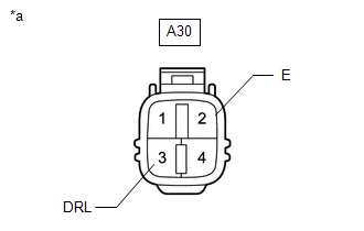
| (a) Disconnect the clearance light assembly LH connector. |
|
(b) Measure the voltage according to the value(s) in the table below.
Standard Voltage:
| Tester Connection | Switch Condition | Specified Condition |
|---|---|---|
| A30-3 (DRL) - Body ground | Power switch on (IG) | 11 to 14 V |
(c) Measure the resistance according to the value(s) in the table below.
Standard Resistance:
| Tester Connection | Condition | Specified Condition |
|---|---|---|
| A30-2 (E) - Body ground | Always | Below 1 Ω |
| NG | | REPAIR OR REPLACE HARNESS OR CONNECTOR |
|
| 6. | CHECK HARNESS AND CONNECTOR (HEADLIGHT LIGHT CONTROL ECU ASSEMBLY LH - CLEARANCE LIGHT ASSEMBLY LH) |
(a) Disconnect the A19 headlight ECU sub-assembly LH connector.
(b) Disconnect the A30 clearance light assembly LH connector.
(c) Measure the resistance according to the value(s) in the table below.
Standard Resistance:
| Tester Connection | Condition | Specified Condition |
|---|---|---|
| A19-8 (RLD2) - A30-4 (DRLC) | Always | Below 1 Ω |
| A19-8 (RLD2) or A30-4 (DRLC) - Body ground | Always | 10 kΩ or higher |
| NG | | REPAIR OR REPLACE HARNESS OR CONNECTOR |
|
| 7. | INSPECT CLEARANCE LIGHT ASSEMBLY LH |
(a) Remove the clearance light assembly LH.
for LED Type Side Turn Signal Light:
Click here
for Bulb Type Slide Turn Signal Light:
Click here
(b) Inspect the clearance light assembly LH.
for LED Type Side Turn Signal Light:
Click here
for Bulb Type Slide Turn Signal Light:
Click here
| OK | | REPLACE HEADLIGHT ECU SUB-ASSEMBLY LH |
| NG | | REPLACE CLEARANCE LIGHT ASSEMBLY LH |
READ NEXT:
 Front Fog Light Circuit
DESCRIPTION Illumination of the front fog lights is controlled by the main body ECU (multiplex network body ECU). WIRING DIAGRAM except Sport Package: for Sport Package: CAUTION / NOTICE / HINT NOT
Hazard Warning Switch Circuit
DESCRIPTION When the combination meter receives a hazard warning signal switch signal, the flasher IC turns on and hazard control is performed. WIRING DIAGRAM CAUTION / NOTICE / HINT NOTICE: When rep
Taillight Relay Circuit
DESCRIPTION Illumination of the taillights and license plate light is controlled by the main body ECU (multiplex network body ECU). WIRING DIAGRAM CAUTION / NOTICE / HINT NOTICE:
Inspect the fuse
SEE MORE:
Registration
REGISTRATION PROCEDURE 1. REGISTER TRANSMITTER CODE HINT:
The vehicle garage door opener records transmitter codes for systems such as garage doors, gates, entry gates, door locks, home lighting systems, security systems or other transmitter code based systems.
The garage door opener is built i
Removal
REMOVAL CAUTION / NOTICE / HINT HINT:
Use the same procedure for the RH and LH sides.
The procedure listed below is for the LH side.
PROCEDURE 1. REMOVE TONNEAU COVER ASSEMBLY Click here 2. REMOVE DECK BOARD ASSEMBLY Click here 3. REMOVE NO. 3 DECK BOARD SUB-ASSEMBLY Click here
