Lexus NX: DC/DC Converter Step Up Voltage Performance (P0CA3-442)
DTC SUMMARY
MALFUNCTION DESCRIPTION
This DTC indicates that it has been detected that the VH voltage cannot be boosted as commanded due to malfunction of the boost converter system. The cause of this malfunction may be one of the following:
- Inverter with converter assembly internal circuit malfunction
- The connectors are not connected properly
DESCRIPTION
The boost converter boosts the 244.8 V DC from the HV battery to a maximum of approximately 650 V DC. The inverter converts the voltage that has been boosted by the boost converter into alternating current, which is used for driving generator (MG1) and motor (MG2). When a motor or generator operates as a generator, the alternating current that it creates is converted into direct current by the inverter. Then the boost converter drops this voltage to direct current of approximately 244.8 V in order to charge the HV battery.
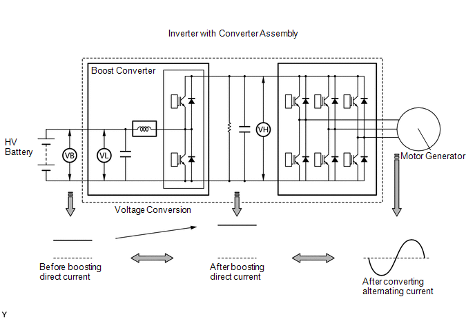
The MG ECU uses a voltage sensor (VL) that is built into the boost converter to detect the high voltage before it is boosted. It also uses a voltage sensor (VH) that is built into the inverter to detect the high voltage after it is boosted. Based on the voltage before and after it is boosted, the MG ECU controls the operation of the boost converter to boost the voltage to the target voltage.
| DTC No. | Detection Item | DTC Detection Condition | Trouble Area | MIL | Warning Indicate |
|---|---|---|---|---|---|
| P0CA3-442 | DC/DC Converter Step Up Voltage Performance | Abnormal voltage execution value: Boosting cannot be performed as requested due to a boost converter system malfunction. (1 trip detection logic) |
| Comes on | Master Warning Light: Comes on |
HINT:
With the vehicle stopped, apply the parking brake and turn the power switch on (READY).
With the shift lever in P, depress the brake pedal firmly, and quickly and fully depress the accelerator pedal.
Immediately after the accelerator pedal is fully depressed, "VH-Voltage after boosting" will be between 400 and 650 V.
Related Data List| DTC No. | Data List |
|---|---|
| P0CA3-442 | VH-Voltage after Boosting |
MONITOR DESCRIPTION
If the difference between the requested boost converter voltage and the actual boost converter voltage exceeds a predetermined value, the MG ECU determines that there is a malfunction of the execution or monitoring of the boost converter voltage. The MG ECU will send information about the malfunction to the hybrid vehicle control ECU. Upon receiving this information, the hybrid vehicle control ECU will illuminate the MIL and store a DTC.
MONITOR STRATEGY
| Related DTCs | P0CA3 (INF 442): Discrepancy between commanded and actual voltage |
| Required sensors/components | Boost converter |
| Frequency of operation | Continuous |
| Duration | TMC's intellectual property |
| MIL operation | 1 driving cycle |
| Sequence of operation | None |
TYPICAL ENABLING CONDITIONS
| The monitor will run whenever the following DTCs are not stored | TMC's intellectual property |
| Other conditions belong to TMC's intellectual property | - |
TYPICAL MALFUNCTION THRESHOLDS
| TMC's intellectual property | - |
COMPONENT OPERATING RANGE
| Hybrid vehicle control ECU | DTC P0CA3 (INF 442) is not detected |
CONFIRMATION DRIVING PATTERN
.png)
- Connect the Techstream to the DLC3.
- Turn the power switch on (IG) and turn the Techstream on.
- Clear the DTCs (even if no DTCs are stored, perform the clear DTC procedure).
- Turn the power switch off and wait for 30 seconds or more.
- Turn the power switch on (IG) and turn the Techstream on.
- Turn the power switch on (READY).
- With the engine stopped and shift lever in P, depress the accelerator pedal to start the engine. [A]
- Enter the following menus: Powertrain / Hybrid Control / Trouble Codes. [B]
-
Read the current DTCs.
HINT:
- If a current DTC is output, the system is malfunctioning.
- If current DTCs are not output, perform the following steps to check for permanent DTCs.
- Check that the permanent DTCs are cleared.
- If the permanent DTCs are not cleared, perform a universal trip, and then check for permanent DTCs again.
CAUTION / NOTICE / HINT
CAUTION:
- Before inspecting the high-voltage system or disconnecting the low voltage connector of the inverter with converter assembly, take safety precautions such as wearing insulated gloves and removing the service plug grip to prevent electrical shocks. After removing the service plug grip, put it in your pocket to prevent other technicians from accidentally reconnecting it while you are working on the high-voltage system.
-
After removing the service plug grip, wait for at least 10 minutes before touching any of the high-voltage connectors or terminals. After waiting for 10 minutes, check the voltage at the terminals in the inspection point in the inverter with converter assembly. The voltage should be 0 V before beginning work.
Click here
.gif)
HINT:
Waiting for at least 10 minutes is required to discharge the high-voltage capacitor inside the inverter with converter assembly.
NOTICE:
After turning the power switch off, waiting time may be required before disconnecting the cable from the negative (-) auxiliary battery terminal. Therefore, make sure to read the disconnecting the cable from the negative (-) auxiliary battery terminal notices before proceeding with work.
Click here
HINT:
After the repair, clear the DTCs and perform the following procedure to check that DTCs are not output.
- Turn the power switch on (READY).
- With the engine stopped and the shift lever in P, depress the accelerator pedal to start the engine.
PROCEDURE
| 1. | CHECK DTC OUTPUT (HYBRID CONTROL) |
(a) Connect the Techstream to the DLC3.
(b) Turn the power switch on (IG).
(c) Enter the following menus: Powertrain / Hybrid Control / Trouble Codes.
(d) Check for DTCs.
Powertrain > Hybrid Control > Trouble Codes| Result | Proceed to |
|---|---|
| P0CA3-442 only is output, or DTCs except the ones in the table below are also output. | A |
| Any of the following DTCs are also output. | B |
| Malfunction Content | Relevant DTC | |
|---|---|---|
| Microcomputer malfunction | P0A1A-151, 166, 658, 791 | Generator Control Module |
| P0A1B-198, 786, 794 | Drive Motor "A" Control Module | |
| P0A1D (all INF codes)* | Hybrid Powertrain Control Module | |
| P1C2A-155 | Generator A/D Converter Circuit | |
| P1C2B-192 | Drive Motor "A" A/D Converter Circuit | |
| P1CA6-156 | Generator Control Module Malfunction | |
| P1CA7-193 | Drive Motor Control Module Malfunction | |
| P1CAC-200 | Generator Position Sensor Angle Malfunction | |
| P1CAD-168 | Drive Motor "A" Position Sensor Angle Malfunction | |
| P1CAF-792 | Generator Position Sensor REF Signal Cycle Malfunction | |
| P1CB0-795 | Drive Motor "A" Position Sensor REF Signal Cycle Malfunction | |
| P1CB2-793 | Generator Position Sensor REF Signal Stop Malfunction | |
| P1CB3-796 | Drive Motor "A" Position Sensor REF Signal Stop Malfunction | |
| P3133-659 | Communication Error from Generator to Drive Motor "A" | |
| P3134-661 | Communication Error from Drive Motor "A" to Generator | |
| Power source circuit malfunction | P06B0-163 | Sensor Power Supply "A" Circuit / Open |
| P06D6-511 | Sensor Reference Voltage "F" Circuit / Open | |
| P06E6-164 | Sensor Power Supply "C" Circuit / Open | |
| P1C73-512 | Sensor Standard Voltage "F" Circuit / Open | |
| Sensor and actuator circuit malfunction | P0A3F-243 | Drive Motor "A" Position Sensor Circuit |
| P0A40-500 | Drive Motor "A" Position Sensor Circuit Range / Performance | |
| P0A41-245 | Drive Motor "A" Position Sensor Circuit Low | |
| P0A45-669 | Drive Motor "B" Position Sensor Circuit | |
| P0A46-671 | Drive Motor "B" Position Sensor Circuit Range / Performance | |
| P0A47-670 | Drive Motor "B" Position Sensor Circuit Low | |
| P0A4B-253 | Generator Position Sensor Circuit | |
| P0A4C-513 | Generator Position Sensor Circuit Range / Performance | |
| P0A4D-255 | Generator Position Sensor Circuit Low | |
| P0BEA-290 | Drive Motor "A" Phase V Current Sensor Circuit Range / Performance | |
| P0BEE-298 | Drive Motor "A" Phase W Current Sensor Circuit Range / Performance | |
| P0BF6-683 | Drive Motor "B" Phase V Current Sensor Circuit Range / Performance | |
| P0BFA-685 | Drive Motor "B" Phase W Current Sensor Circuit Range / Performance | |
| P0E05-328 | Generator Phase V Current Sensor Circuit Range / Performance | |
| P0E09-336 | Generator Phase W Current Sensor Circuit Range / Performance | |
| P1C3C-294 | Drive Motor "A" Phase V Current Sensor Correlation | |
| P1C3D-302 | Drive Motor "A" Phase W Current Sensor Correlation | |
| P1C3E-333 | Generator Phase V Current Sensor Correlation | |
| P1C3F-341 | Generator Phase W Current Sensor Correlation | |
| P1C4A-288 | Drive Motor "A" Phase V Current Sensor Sub Circuit Range / Performance | |
| P1C4F-296 | Drive Motor "A" Phase W Current Sensor Sub Circuit Range / Performance | |
| P1C54-326 | Generator Phase V Current Sensor Sub Circuit Range / Performance | |
| P1C59-334 | Generator Phase W Current Sensor Sub Circuit Range / Performance | |
| P1C6D-501 | Drive Motor "A" Phase V Current Sensor Offset Range / Performance | |
| P1C6E-502 | Drive Motor "A" Phase W Current Sensor Offset Range / Performance | |
| P1C6F-688 | Drive Motor "B" Phase V Current Sensor Offset Range / Performance | |
| P1C70-689 | Drive Motor "B" Phase W Current Sensor Offset Range / Performance | |
| P1C71-515 | Generator Phase V Current Sensor Offset Range / Performance | |
| P1C72-516 | Generator Phase W Current Sensor Offset Range / Performance | |
| P33C1-684 | Drive Motor "B" Phase V Current Sensor Sub Circuit Range / Performance | |
| P33C6-686 | Drive Motor "B" Phase W Current Sensor Sub Circuit Range / Performance | |
| P33D8-677 | Drive Motor "B" Phase V Current Sensor Correlation | |
| P33D9-678 | Drive Motor "A" Phase W Current Sensor Correlation | |
| System malfunction | P0A1A-517, 809 | Generator Control Module |
| P0A1B-503, 505, 547, 554, 806 | Drive Motor "A" Control Module | |
| P0A1C-693, 812 | Drive Motor "B" Control Module | |
| P0A40-504, 506, 549, 556, 808 | Drive Motor "A" Position Sensor Circuit Range / Performance | |
| P0A46-695, 814 | Drive Motor "B" Position Sensor Circuit Range / Performance | |
| P0A4C-518, 811 | Generator Position Sensor Circuit Range / Performance | |
| P0A78-279, 287, 548, 555, 807 | Drive Motor "A" Inverter Performance | |
| P0A79-694, 716, 813 | Drive Motor "B" Inverter Performance | |
| P0A7A-325, 810 | Generator Inverter Performance | |
| P0A90-509 | Drive Motor "A" Performance | |
| P0A92-521 | Hybrid Generator Performance | |
| P0C76-523 | Hybrid Battery System Discharge Time Too Long | |
| P0D2E-586 | Drive Motor "A" Inverter Voltage Sensor Circuit Range / Performance | |
| P0D2F-266 | Drive Motor "A" Inverter Voltage Sensor Circuit Low | |
| P0D30-267 | Drive Motor "A" Inverter Voltage Sensor Circuit High | |
| P0E32-585 | DC/DC Converter Voltage Sensor "A" Range / Performance | |
| P0E33-589 | DC/DC Converter Voltage Sensor "A" Low | |
| P0E34-590 | DC/DC Converter Voltage Sensor "A" High | |
| P1C2D-587 | Hybrid Battery Voltage / DC/DC Converter Voltage Correlation | |
HINT:
- *1: If any INF codes are output for this DTC, refer to the corresponding diagnostic procedure.
-
P0CA3-442 may be output as a result of the malfunction indicated by the DTCs above.
- The chart above is listed in inspection order of priority.
- Check DTCs that are output at the same time by following the listed order. (The main cause of the malfunction can be determined without performing unnecessary inspections.)
(e) Turn the power switch off.
| B | .gif) | GO TO DTC CHART (HYBRID CONTROL SYSTEM) |
|
.gif)
| 2. | CHECK CONNECTOR CONNECTION CONDITION (INVERTER WITH CONVERTER ASSEMBLY CONNECTOR) |
Click here
| Result | Proceed to |
|---|---|
| OK | A |
| NG (The connector is not connected securely.) | B |
| NG (The terminals are not making secure contact or are deformed, or water or foreign matter exists in the connector.) | C |
| A | | REPLACE INVERTER WITH CONVERTER ASSEMBLY |
| B | | CONNECT SECURELY |
| C | | REPAIR OR REPLACE HARNESS OR CONNECTOR |
READ NEXT:
 Drive Motor "A" Inverter Voltage Sensor Circuit Range / Performance (P0D2E-565)
DTC SUMMARY MALFUNCTION DESCRIPTION VH voltage sensor signal malfunction in the inverter for the motor. Internal inverter malfunction
Internal circuit malfunction in the inverter for the motor
Ma
Drive Motor "A" Inverter Voltage Sensor Circuit Low (P0D2F-266,P0D30-267)
DESCRIPTION The inverter contains a three-phase bridge circuit, which consists of 6 power transistors (IGBTs) each for the generator (MG1), motor (MG2) and rear motor (MGR). The inverter converts high
Generator Phase V Current Sensor Circuit Range / Performance (P0E05-328,...,P1C72-516)
DTC SUMMARY MALFUNCTION DESCRIPTION These DTCs indicate the current sensor value is abnormal. The cause of this malfunction may be one of the following: Internal inverter malfunction
Inverter with
SEE MORE:
How To Proceed With Troubleshooting
CAUTION / NOTICE / HINT HINT:
Use the following procedure to troubleshoot the sliding roof system.
*: Use the Techstream.
PROCEDURE 1. VEHICLE BROUGHT TO WORKSHOP
NEXT 2. CUSTOMER PROBLEM ANALYSIS HINT:
In troubleshooting, confirm that the problem sympto
Components
COMPONENTS ILLUSTRATION *1 COLUMN HOLE COVER SILENCER SHEET *2 COMBINATION SWITCH ASSEMBLY WITH SPIRAL CABLE SUB-ASSEMBLY *3 ELECTRIC POWER STEERING COLUMN SUB-ASSEMBLY *4 NO. 1 AIR DUCT *5 NO. 2 STEERING INTERMEDIATE SHAFT ASSEMBLY *6 LOWER STEERING COLUMN COVER *7
