- Open or short circuit in the rear motor coils
- Internal rear motor malfunction (iron particles or damage from foreign objects)
Lexus NX: Drive Motor "B" Inverter Performance (P0A79-696)
Lexus NX Service Manual / Engine & Hybrid System / 2ar-fxe (hybrid / Battery Control) / Hybrid Control System / Drive Motor "B" Inverter Performance (P0A79-696)
DTC SUMMARY
MALFUNCTION DESCRIPTION
This DTC indicates a malfunction inside the inverter for the rear motor. The cause of this malfunction may be one of the following:
| Area | Main Malfunction Description | Step |
|---|---|---|
| Inverter low-voltage circuit | The connectors are not connected properly | 3 |
| Hybrid cooling system | Coolant is leaking, insufficient coolant level, frozen or the passenger of coolant is clogged. | 4 |
| Rear motor resolver | Open or short circuit in the rear motor resolver | 5 |
| Rear motor | | 6 |
| Inverter |
| 7 |
DESCRIPTION
For a description of the inverter.
Click here .gif)
If the rear motor inverter overheats, has a circuit malfunction or internal short, the inverter transmits this information to the MG ECU via the rear motor inverter fail signal line.
HINT:
The term "drive motor B" indicates the rear motor (MGR).
| DTC No. | Detection Item | DTC Detection Condition | Trouble Area | MIL | Warning Indicate |
|---|---|---|---|---|---|
| P0A79-696 | Drive Motor "B" Inverter Performance | Rear motor inverter fail signal detected (circuit malfunction) (1 trip detection logic) |
| Comes on | Master Warning Light: Comes on |
MONITOR DESCRIPTION
If the rear motor inverter detects a circuit malfunction, it will transmit a rear motor inverter fail signal to the MG ECU. The MG ECU will send information about the malfunction to the hybrid vehicle control ECU. Upon receiving this information, the hybrid vehicle control ECU will illuminate the MIL and store a DTC.
MONITOR STRATEGY
| Related DTCs | P0A79 (INF 696): RFIV detection (circuit malfunction) |
| Required sensors/components | Rear motor inverter |
| Frequency of operation | Continuous |
| Duration | TMC's intellectual property |
| MIL operation | 1 driving cycle |
| Sequence of operation | None |
TYPICAL ENABLING CONDITIONS
| The monitor will run whenever the following DTCs are not stored | TMC's intellectual property |
| Other conditions belong to TMC's intellectual property | - |
TYPICAL MALFUNCTION THRESHOLDS
| TMC's intellectual property | - |
COMPONENT OPERATING RANGE
| Hybrid vehicle control ECU | DTC P0A79 (INF 696) is not detected |
CONFIRMATION DRIVING PATTERN
- Connect the Techstream to the DLC3.
- Turn the power switch on (IG) and turn the Techstream on.
- Clear the DTCs (even if no DTCs are stored, perform the clear DTC procedure).
- Turn the power switch off and wait for 30 seconds or more.
- Turn the power switch on (IG) and turn the Techstream on.
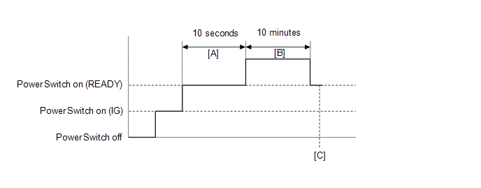
- Turn the power switch on (READY).
-
With the shift lever in P, wait for 10 seconds. [A]
HINT:
Check that there are no abnormalities (abnormal sounds, coolant leaks, etc.).
- Perform a road test according to the freeze frame data item "Vehicle Spd" for approximately 10 minutes. [B]
- Enter the following menus: Powertrain / Hybrid Control / Trouble Codes. [C]
-
Read the current DTCs.
HINT:
- If a current DTC is output, the system is malfunctioning.
- If current DTCs are not output, perform the following steps to check for permanent DTCs.
- Check that the permanent DTCs are cleared.
- If the permanent DTCs are not cleared, perform a universal trip, and then check for permanent DTCs again.
WIRING DIAGRAM
Refer to the wiring diagram for the rear motor resolver circuit.
Click here
Refer to the wiring diagram for the rear motor high-voltage circuit.
Click here
Refer to the wiring diagram for the inverter low-voltage circuit.
Click here
CAUTION / NOTICE / HINT
CAUTION:
- Before inspecting the high-voltage system or disconnecting the low voltage connector of the inverter with converter assembly, take safety precautions such as wearing insulated gloves and removing the service plug grip to prevent electrical shocks. After removing the service plug grip, put it in your pocket to prevent other technicians from accidentally reconnecting it while you are working on the high-voltage system.
-
After removing the service plug grip, wait for at least 10 minutes before touching any of the high-voltage connectors or terminals. After waiting for 10 minutes, check the voltage at the terminals in the inspection point in the inverter with converter assembly. The voltage should be 0 V before beginning work.
Click here
HINT:
Waiting for at least 10 minutes is required to discharge the high-voltage capacitor inside the inverter with converter assembly.
NOTICE:
After turning the power switch off, waiting time may be required before disconnecting the cable from the negative (-) auxiliary battery terminal. Therefore, make sure to read the disconnecting the cable from the negative (-) auxiliary battery terminal notices before proceeding with work.
Click here
HINT:
After the repair, clear the DTCs and perform the following procedure to check that DTCs are not output.
- Turn the power switch on (READY) and wait for 5 seconds or more.
- Perform a road test according to the freeze frame data item "Vehicle Spd" for approximately 10 minutes.
PROCEDURE
| 1. | CHECK DTC OUTPUT (HYBRID CONTROL) |
(a) Connect the Techstream to the DLC3.
(b) Turn the power switch on (IG).
(c) Enter the following menus: Powertrain / Hybrid Control / Trouble Codes.
(d) Check for DTCs.
Powertrain > Hybrid Control > Trouble CodesNOTICE:
- If P0A79-716 is output, troubleshoot it first. After completing the troubleshooting for P0A79-716, perform troubleshooting for this DTC.
- Parts repaired or replaced during troubleshooting for P0A79-716 do not need to be re-inspected in this diagnostic procedure.
(e) Turn the power switch off.
| P0A79-716 is also output. | .gif) | GO TO DTC CHART (HYBRID CONTROL SYSTEM) |
|
.gif)
| 2. | CHECK DTC OUTPUT (HYBRID CONTROL) |
(a) Connect the Techstream to the DLC3.
(b) Turn the power switch on (IG).
(c) Enter the following menus: Powertrain / Hybrid Control / Trouble Codes.
(d) Check for DTCs.
Powertrain > Hybrid Control > Trouble CodesHINT:
- If P0A79-716 was not output in step 1 of this diagnostic procedure, check Table 1 below.
- If P0A79-716 was output in step 1 of this diagnostic procedure, diagnose that DTC first, then check Table 2 below.
| Result | Proceed to |
|---|---|
| P0A79-696 only is output, or DTCs except the ones in the tables below are also output. | A |
| Any of the following DTCs are also output. | B |
| Malfunction Content | Relevant DTC | |
|---|---|---|
| Microcomputer malfunction | P0A1A-151, 166, 658, 791 | Generator Control Module |
| P0A1B-198, 786, 794 | Drive Motor "A" Control Module | |
| P0A1C-709, 710, 713, 797 | Drive Motor "B" Control Module | |
| P0A1D (all INF codes)*1 | Hybrid Powertrain Control Module | |
| P1C2A-155 | Generator A/D Converter Circuit | |
| P1C2B-192 | Drive Motor "A" A/D Converter Circuit | |
| P1C2C-706 | Drive Motor "B" A/D Converter Circuit | |
| P1CA6-156 | Generator Control Module Malfunction | |
| P1CA7-193 | Drive Motor Control Module Malfunction | |
| P1CA8-708 | Drive Motor "B" Control Module Malfunction | |
| P1CAC-200 | Generator Position Sensor Angle Malfunction | |
| P1CAD-168 | Drive Motor "A" Position Sensor Angle Malfunction | |
| P1CAE-715 | Drive Motor "B" Position Sensor Angle Malfunction | |
| P1CAF-792 | Generator Position Sensor REF Signal Cycle Malfunction | |
| P1CB0-795 | Drive Motor "A" Position Sensor REF Signal Cycle Malfunction | |
| P1CB1-798 | Drive Motor "B" Position Sensor REF Signal Cycle Malfunction | |
| P1CB2-793 | Generator Position Sensor REF Signal Stop Malfunction | |
| P1CB3-796 | Drive Motor "A" Position Sensor REF Signal Stop Malfunction | |
| P1CB4-799 | Drive Motor "B" Position Sensor REF Signal Stop Malfunction | |
| P3133-659 | Communication Error from Generator to Drive Motor "A" | |
| P3134-661 | Communication Error from Drive Motor "A" to Generator | |
| Power source circuit malfunction | P06B0-163 | Sensor Power Supply "A" Circuit / Open |
| P06D6-511 | Sensor Reference Voltage "F" Circuit / Open | |
| P06E6-164 | Sensor Power Supply "C" Circuit / Open | |
| P1C73-512 | Sensor Standard Voltage "F" Circuit / Open | |
| Sensor and actuator circuit malfunction | P0A3F-243 | Drive Motor "A" Position Sensor Circuit |
| P0A40-500 | Drive Motor "A" Position Sensor Circuit Range / Performance | |
| P0A41-245 | Drive Motor "A" Position Sensor Circuit Low | |
| P0A45-669 | Drive Motor "B" Position Sensor Circuit | |
| P0A46-671 | Drive Motor "B" Position Sensor Circuit Range / Performance | |
| P0A47-670 | Drive Motor "B" Position Sensor Circuit Low | |
| P0A4B-253 | Generator Position Sensor Circuit | |
| P0A4C-513 | Generator Position Sensor Circuit Range / Performance | |
| P0A4D-255 | Generator Position Sensor Circuit Low | |
| P0BEA-290 | Drive Motor "A" Phase V Current Sensor Circuit Range / Performance | |
| P0BEE-298 | Drive Motor "A" Phase W Current Sensor Circuit Range / Performance | |
| P0BF6-683 | Drive Motor "B" Phase V Current Sensor Circuit Range / Performance | |
| P0BFA-685 | Drive Motor "B" Phase W Current Sensor Circuit Range / Performance | |
| P0C73-776 | Motor Electronics Coolant Pump "A" Control Performance | |
| P0E05-328 | Generator Phase V Current Sensor Circuit Range / Performance | |
| P0E09-336 | Generator Phase W Current Sensor Circuit Range / Performance | |
| P1C3C-294 | Drive Motor "A" Phase V Current Sensor Correlation | |
| P1C3D-302 | Drive Motor "A" Phase W Current Sensor Correlation | |
| P1C3E-333 | Generator Phase V Current Sensor Correlation | |
| P1C3F-341 | Generator Phase W Current Sensor Correlation | |
| P1C4A-288 | Drive Motor "A" Phase V Current Sensor Sub Circuit Range / Performance | |
| P1C4F-296 | Drive Motor "A" Phase W Current Sensor Sub Circuit Range / Performance | |
| P1C54-326 | Generator Phase V Current Sensor Sub Circuit Range / Performance | |
| P1C59-334 | Generator Phase W Current Sensor Sub Circuit Range / Performance | |
| P1C6D-501 | Drive Motor "A" Phase V Current Sensor Offset Range / Performance | |
| P1C6E-502 | Drive Motor "A" Phase W Current Sensor Offset Range / Performance | |
| P1C6F-688 | Drive Motor "B" Phase V Current Sensor Offset Range / Performance | |
| P1C70-689 | Drive Motor "B" Phase W Current Sensor Offset Range / Performance | |
| P1C71-515 | Generator Phase V Current Sensor Offset Range / Performance | |
| P1C72-516 | Generator Phase W Current Sensor Offset Range / Performance | |
| P314A-828 | Inverter Coolant Pump Speed Signal | |
| P33C1-684 | Drive Motor "B" Phase V Current Sensor Sub Circuit Range / Performance | |
| P33C6-686 | Drive Motor "B" Phase W Current Sensor Sub Circuit Range / Performance | |
| P33D8-677 | Drive Motor "B" Phase V Current Sensor Correlation | |
| P33D9-678 | Drive Motor "A" Phase W Current Sensor Correlation | |
| System malfunction | P0A1A-517, 809 | Generator Control Module |
| P0A1B-503, 505, 547, 554, 806 | Drive Motor "A" Control Module | |
| P0A1C-118, 124, 169, 693, 812 | Drive Motor "B" Control Module | |
| P0A40-504, 506, 549, 556, 808 | Drive Motor "A" Position Sensor Circuit Range / Performance | |
| P0A46-120, 126, 171, 695, 814 | Drive Motor "B" Position Sensor Circuit Range / Performance | |
| P0A4C-518, 811 | Generator Position Sensor Circuit Range / Performance | |
| P0A78-113, 128, 279, 284, 287, 548, 555, 807 | Drive Motor "A" Inverter Performance | |
| P0A79-119, 125, 136, 170, 692, 694, 712, 813 | Drive Motor "B" Inverter Performance | |
| P0A7A-122, 130, 322, 325, 810 | Generator Inverter Performance | |
| P0A90-509 | Drive Motor "A" Performance | |
| P0A91-702 | Drive Motor "B" Performance | |
| P0A92-521 | Hybrid Generator Performance | |
| P0C19-306 | Drive Motor "A" Torque Delivered Performance | |
| P0C1A-704 | Drive Motor "B" Torque Delivered Performance | |
| P0C76-523 | Hybrid Battery System Discharge Time Too Long | |
| P0CA3-442 | DC/DC Converter Step Up Voltage Performance | |
| P0D2E-586 | Drive Motor "A" Inverter Voltage Sensor Circuit Range / Performance | |
| P0D2F-266 | Drive Motor "A" Inverter Voltage Sensor Circuit Low | |
| P0D30-267 | Drive Motor "A" Inverter Voltage Sensor Circuit High | |
| P0E32-585 | DC/DC Converter Voltage Sensor "A" Range / Performance | |
| P0E33-589 | DC/DC Converter Voltage Sensor "A" Low | |
| P0E34-590 | DC/DC Converter Voltage Sensor "A" High | |
| P0E71-344 | Generator Torque Delivered Performance | |
| P1C2D-587 | Hybrid Battery Voltage / DC/DC Converter Voltage Correlation | |
| Malfunction Content | Relevant DTC | |
|---|---|---|
| Microcomputer malfunction | P0A1A-151, 166, 658, 791 | Generator Control Module |
| P0A1B-198, 786, 794 | Drive Motor "A" Control Module | |
| P0A1C-709, 710, 713, 797 | Drive Motor "B" Control Module | |
| P0A1D (all INF codes)*1 | Hybrid Powertrain Control Module | |
| P1C2A-155 | Generator A/D Converter Circuit | |
| P1C2B-192 | Drive Motor "A" A/D Converter Circuit | |
| P1C2C-706 | Drive Motor "B" A/D Converter Circuit | |
| P1CA6-156 | Generator Control Module Malfunction | |
| P1CA7-193 | Drive Motor Control Module Malfunction | |
| P1CA8-708 | Drive Motor "B" Control Module Malfunction | |
| P1CAC-200 | Generator Position Sensor Angle Malfunction | |
| P1CAD-168 | Drive Motor "A" Position Sensor Angle Malfunction | |
| P1CAE-715 | Drive Motor "B" Position Sensor Angle Malfunction | |
| P1CAF-792 | Generator Position Sensor REF Signal Cycle Malfunction | |
| P1CB0-795 | Drive Motor "A" Position Sensor REF Signal Cycle Malfunction | |
| P1CB1-798 | Drive Motor "B" Position Sensor REF Signal Cycle Malfunction | |
| P1CB2-793 | Generator Position Sensor REF Signal Stop Malfunction | |
| P1CB3-796 | Drive Motor "A" Position Sensor REF Signal Stop Malfunction | |
| P1CB4-799 | Drive Motor "B" Position Sensor REF Signal Stop Malfunction | |
| P3133-659 | Communication Error from Generator to Drive Motor "A" | |
| P3134-661 | Communication Error from Drive Motor "A" to Generator | |
| Power source circuit malfunction | P06B0-163 | Sensor Power Supply "A" Circuit / Open |
| P06D6-511 | Sensor Reference Voltage "F" Circuit / Open | |
| P06E6-164 | Sensor Power Supply "C" Circuit / Open | |
| P1C73-512 | Sensor Standard Voltage "F" Circuit / Open | |
| Sensor and actuator circuit malfunction | P0A3F-243 | Drive Motor "A" Position Sensor Circuit |
| P0A40-500 | Drive Motor "A" Position Sensor Circuit Range / Performance | |
| P0A41-245 | Drive Motor "A" Position Sensor Circuit Low | |
| P0A45-669 | Drive Motor "B" Position Sensor Circuit | |
| P0A46-671 | Drive Motor "B" Position Sensor Circuit Range / Performance | |
| P0A47-670 | Drive Motor "B" Position Sensor Circuit Low | |
| P0A4B-253 | Generator Position Sensor Circuit | |
| P0A4C-513 | Generator Position Sensor Circuit Range / Performance | |
| P0A4D-255 | Generator Position Sensor Circuit Low | |
| P0BEA-290 | Drive Motor "A" Phase V Current Sensor Circuit Range / Performance | |
| P0BEE-298 | Drive Motor "A" Phase W Current Sensor Circuit Range / Performance | |
| P0C73-776 | Motor Electronics Coolant Pump "A" Control Performance | |
| P0E05-328 | Generator Phase V Current Sensor Circuit Range / Performance | |
| P0E09-336 | Generator Phase W Current Sensor Circuit Range / Performance | |
| P1C3C-294 | Drive Motor "A" Phase V Current Sensor Correlation | |
| P1C3D-302 | Drive Motor "A" Phase W Current Sensor Correlation | |
| P1C3E-333 | Generator Phase V Current Sensor Correlation | |
| P1C3F-341 | Generator Phase W Current Sensor Correlation | |
| P1C4A-288 | Drive Motor "A" Phase V Current Sensor Sub Circuit Range / Performance | |
| P1C4F-296 | Drive Motor "A" Phase W Current Sensor Sub Circuit Range / Performance | |
| P1C54-326 | Generator Phase V Current Sensor Sub Circuit Range / Performance | |
| P1C59-334 | Generator Phase W Current Sensor Sub Circuit Range / Performance | |
| P1C6D-501 | Drive Motor "A" Phase V Current Sensor Offset Range / Performance | |
| P1C6E-502 | Drive Motor "A" Phase W Current Sensor Offset Range / Performance | |
| P1C71-515 | Generator Phase V Current Sensor Offset Range / Performance | |
| P1C72-516 | Generator Phase W Current Sensor Offset Range / Performance | |
| P314A-828 | Inverter Coolant Pump Speed Signal | |
| P33D8-677 | Drive Motor "B" Phase V Current Sensor Correlation | |
| P33D9-678 | Drive Motor "A" Phase W Current Sensor Correlation | |
| System malfunction | P0A1A-517, 809 | Generator Control Module |
| P0A1B-503, 505, 547, 554, 806 | Drive Motor "A" Control Module | |
| P0A1C-118, 124, 169, 693, 812 | Drive Motor "B" Control Module | |
| P0A40-504, 506, 549, 556, 808 | Drive Motor "A" Position Sensor Circuit Range / Performance | |
| P0A46-120, 126, 171, 695, 814 | Drive Motor "B" Position Sensor Circuit Range / Performance | |
| P0A4C-518, 811 | Generator Position Sensor Circuit Range / Performance | |
| P0A78-113, 128, 279, 284, 287, 548, 555, 807 | Drive Motor "A" Inverter Performance | |
| P0A79-119, 125, 136, 170, 692, 694, 712, 813 | Drive Motor "B" Inverter Performance | |
| P0A7A-122, 130, 322, 325, 810 | Generator Inverter Performance | |
| P0A90-509 | Drive Motor "A" Performance | |
| P0A92-521 | Hybrid Generator Performance | |
| P0C19-306 | Drive Motor "A" Torque Delivered Performance | |
| P0C76-523 | Hybrid Battery System Discharge Time Too Long | |
| P0CA3-442 | DC/DC Converter Step Up Voltage Performance | |
| P0D2E-586 | Drive Motor "A" Inverter Voltage Sensor Circuit Range / Performance | |
| P0D2F-266 | Drive Motor "A" Inverter Voltage Sensor Circuit Low | |
| P0D30-267 | Drive Motor "A" Inverter Voltage Sensor Circuit High | |
| P0E32-585 | DC/DC Converter Voltage Sensor "A" Range / Performance | |
| P0E33-589 | DC/DC Converter Voltage Sensor "A" Low | |
| P0E34-590 | DC/DC Converter Voltage Sensor "A" High | |
| P0E71-344 | Generator Torque Delivered Performance | |
| P1C2D-587 | Hybrid Battery Voltage / DC/DC Converter Voltage Correlation | |
HINT:
- *1: If any INF codes are output for this DTC, refer to the corresponding diagnostic procedure.
-
P0A79-696 may be output as a result of the malfunction indicated by the DTCs above.
- The chart above is listed in inspection order of priority.
- Check DTCs that are output at the same time by following the listed order. (The main cause of the malfunction can be determined without performing unnecessary inspections.)
(e) Turn the power switch off.
| B | | GO TO DTC CHART (HYBRID CONTROL SYSTEM) |
|
| 3. | CHECK CONNECTOR CONNECTION CONDITION (INVERTER WITH CONVERTER ASSEMBLY CONNECTOR) |
Click here
| Result | Proceed to |
|---|---|
| OK | A |
| NG (The connector is not connected securely.) | B |
| NG (The terminals are not making secure contact or are deformed, or water or foreign matter exists in the connector.) | C |
| B | | CONNECT SECURELY |
| C | | REPAIR OR REPLACE HARNESS OR CONNECTOR |
|
| 4. | CHECK COOLING SYSTEM |
Click here
|
| 5. | CHECK REAR MOTOR RESOLVER CIRCUIT |
Click here
|
| 6. | CHECK REAR MOTOR HIGH-VOLTAGE CIRCUIT |
Click here
|
| 7. | CHECK INVERTER LOW-VOLTAGE CIRCUIT |
Click here
HINT:
If the "Inverter Low-voltage Circuit" inspection results are normal, perform the next step.
| NEXT | | REPLACE INVERTER WITH CONVERTER ASSEMBLY |
READ NEXT:
 Generator Inverter Performance (P0A7A-122)
DTC SUMMARY MALFUNCTION DESCRIPTION This DTC indicates that a large current flowed in the inverter for the generator. The cause of this malfunction may be one of the following: Area Main Malfunct
Generator Inverter Performance (P0A7A-325,P0A7A-810)
DTC SUMMARY MALFUNCTION DESCRIPTION These DTCs indicate that a large current flowed in the inverter for the generator. The cause of this malfunction may be one of the following: Internal inverter mal
Drive Motor "A" Performance (P0A90-251)
DTC SUMMARY MALFUNCTION DESCRIPTION This DTC indicates that magnetic force deterioration of the permanent magnet located in the rotor inside the motor has been detected. The cause of this malfunction
SEE MORE:
Data List / Active Test
DATA LIST / ACTIVE TEST DATA LIST HINT: Using the Techstream to read the Data List allows the values or states of switches, sensors, actuators and other items to be read without removing any parts. This non-intrusive inspection can be very useful because intermittent conditions or signals may be dis
Tonneau Cover Assembly
ComponentsCOMPONENTS ILLUSTRATION *1 NO. 1 TONNEAU COVER HOLDER CAP *2 TONNEAU COVER CAP PLATE *3 REAR TONNEAU COVER CAP *4 CUSHION *5 STRING - - DisassemblyDISASSEMBLY CAUTION / NOTICE / HINT HINT:
Use the same procedure for the RH and LH sides.
The procedure
© 2016-2026 Copyright www.lexunx.com
