Lexus NX: Drive Motor "B" Temperature Sensor Circuit Low (P0A32-666,P0A33-665)
DESCRIPTION
Refer to the description for DTC P0A31-668.
Click here .gif)
HINT:
The term "drive motor B" indicates the rear motor (MGR).
| DTC No. | Detection Item | DTC Detection Condition | Trouble Area | MIL | Warning Indicate |
|---|---|---|---|---|---|
| P0A32-666 | Drive Motor "B" Temperature Sensor Circuit Low | Line short or short to ground in rear motor temperature sensor circuit (1 trip detection logic) |
| Does not come on | Master Warning Light: Comes on |
| P0A33-665 | Drive Motor "B" Temperature Sensor Circuit High | Open or short to +B in rear motor temperature sensor circuit (1 trip detection logic) |
| Does not come on | Master Warning Light: Comes on |
HINT:
After confirming that DTC P0A32-666 or P0A33-665 is output, use the Techstream to check "Rear Motor Temp" in the Data List.
| Displayed Temperature | Malfunction |
|---|---|
| -40°C (-40°F) | Open circuit or short to +B |
| 215°C (419°F) | Short circuit or short to ground |
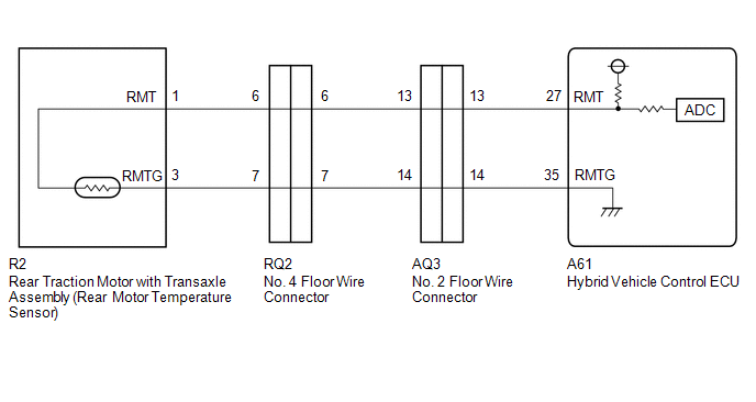
WIRING DIAGRAM
CAUTION / NOTICE / HINT
HINT:
After the repair, clear the DTCs and perform the following procedure to check that DTCs are not output.
- Turn the power switch on (IG) and wait for 5 seconds or more.
PROCEDURE
| 1. | CHECK CONNECTOR CONNECTION CONDITION (HYBRID VEHICLE CONTROL ECU CONNECTOR) |
Click here
| Result | Proceed to |
|---|---|
| OK | A |
| NG (The connector is not connected securely.) | B |
| NG (The terminals are not making secure contact or are deformed, or water or foreign matter exists in the connector.) | C |
| B | .gif) | CONNECT SECURELY |
| C | | REPAIR OR REPLACE HARNESS OR CONNECTOR |
|
.gif)
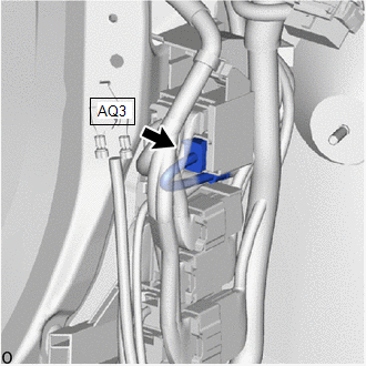
| 2. | CHECK CONNECTOR CONNECTION CONDITION (NO. 2 FLOOR WIRE CONNECTOR) |
| (a) Check the connection condition of the rear motor temperature intermediate connector AQ3 (No. 2 floor wire) and the contact pressure of each terminal. Check the terminals for deformation, and check the connector for water ingress and foreign matter. Click here OK: - The connector is connected securely. - The terminals are not deformed and are connected securely. - No water or foreign matter in the connector. |
|
| Result | Proceed to |
|---|---|
| OK | A |
| NG (The connector is not connected securely.) | B |
| NG (The terminals are not making secure contact or are deformed, or water or foreign matter exists in the connector.) | C |
| B | | CONNECT SECURELY |
| C | | REPAIR OR REPLACE HARNESS OR CONNECTOR |
|
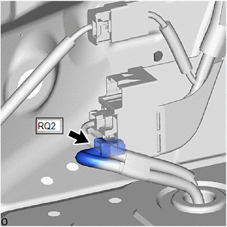
| 3. | CHECK CONNECTOR CONNECTION CONDITION (NO. 4 FLOOR WIRE CONNECTOR) |
| (a) Check the connection condition of the rear motor temperature intermediate connector RQ2 (No. 4 floor wire) and the contact pressure of each terminal. Check the terminals for deformation, and check the connector for water ingress and foreign matter. Click here OK: - The connector is connected securely. - The terminals are not deformed and are connected securely. - No water or foreign matter in the connector. |
|
| Result | Proceed to |
|---|---|
| OK | A |
| NG (The connector is not connected securely.) | B |
| NG (The terminals are not making secure contact or are deformed, or water or foreign matter exists in the connector.) | C |
| B | | CONNECT SECURELY |
| C | | REPAIR OR REPLACE HARNESS OR CONNECTOR |
|
| 4. | READ VALUE USING GTS (REAR MOTOR TEMP) |
(a) Connect the Techstream to the DLC3.
(b) Turn the power switch on (IG).
(c) Enter the following menus: Powertrain / Hybrid Control / Data List / Rear Motor Temp.
(d) Read the Data List.
Powertrain > Hybrid Control > Data List| Tester Display |
|---|
| Rear Motor Temp |
| Result | Proceed to |
|---|---|
| -40°C (-40°F) | A |
| 215°C (419°F) | B |
| Same as actual temperature | C |
(e) Turn the power switch off.
| B | | GO TO STEP 9 |
| C | | REPAIR OR REPLACE HARNESS OR CONNECTOR |
|
| 5. | READ VALUE USING GTS (CHECK WIRE HARNESS OPEN CIRCUIT) |
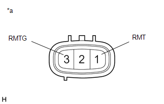
(a) Disconnect the RQ2 No. 4 floor wire connector.
(b) Connect terminals 7 (RMTG) and 6 (RMT) of the RQ2 No. 4 floor wire connector (hybrid vehicle control ECU side).
(c) Read the Data List.
Powertrain > Hybrid Control > Data List| Tester Display |
|---|
| Rear Motor Temp |
OK:
| Tester Display | Condition | Specified Condition |
|---|---|---|
| Rear Motor Temp | Terminals RQ2-7 (RMTG) and RQ2-6 (RMT) connected Power switch on (IG) | 215°C (419°F) |
(d) Turn the power switch off.
(e) Reconnect the RQ2 No. 4 floor wire connector.
| NG | | GO TO STEP 8 |
|
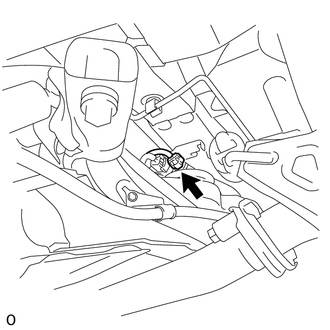
| 6. | CHECK CONNECTOR CONNECTION CONDITION (REAR MOTOR TEMPERATURE SENSOR CONNECTOR) |
| (a) Check the connection condition of the rear motor temperature sensor connector and the contact pressure of each terminal. Check the terminals for deformation, and check the connector for water ingress and foreign matter. Click here OK: - The connector is connected securely. - The terminals are not deformed and are connected securely. - No water or foreign matter in the connector. |
|
| Result | Proceed to |
|---|---|
| OK | A |
| NG (The connector is not connected securely.) | B |
| NG (The terminals are not making secure contact or are deformed, or water or foreign matter exists in the connector.) | C |
| B | | CONNECT SECURELY |
| C | | REPAIR OR REPLACE HARNESS OR CONNECTOR |
|
| 7. | INSPECT REAR TRACTION MOTOR WITH TRANSAXLE ASSEMBLY (REAR MOTOR TEMPERATURE SENSOR) |
| (a) Disconnect the R2 rear motor temperature sensor connector. |
|
| (b) Measure the resistance according to the value(s) in the table below. Standard Resistance:
|
|
(c) Reconnect the R2 rear motor temperature sensor connector.
| OK | | REPAIR OR REPLACE HARNESS OR CONNECTOR (REAR MOTOR TEMPERATURE SENSOR - NO. 4 FLOOR WIRE) |
| NG | | REPLACE REAR TRACTION MOTOR WITH TRANSAXLE ASSEMBLY |
| 8. | CHECK HYBRID VEHICLE CONTROL ECU |
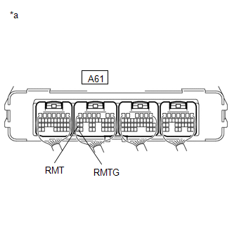
| (a) Connect terminals 27 (RMT) and 35 (RMTG) of the A61 hybrid vehicle control ECU connector. |
|
(b) Connect the Techstream to the DLC3.
(c) Enter the following menus: Powertrain / Hybrid Control / Data List / Rear Motor Temp.
(d) Read the Data List.
Powertrain > Hybrid Control > Data List| Tester Display |
|---|
| Rear Motor Temp |
| Tester Display | Condition | Specified Condition |
|---|---|---|
| Rear Motor Temp | Terminals A61-27 (RMT) and A61-35 (RMTG) connected Power switch on (IG) | 215°C (419°F) |
(e) Turn the power switch off.
| OK | | REPAIR OR REPLACE HARNESS OR CONNECTOR |
| NG | | REPLACE HYBRID VEHICLE CONTROL ECU |
| 9. | READ VALUE USING GTS (CHECK WIRE HARNESS SHORT CIRCUIT) |
(a) Disconnect the RQ2 No. 4 floor wire connector.
(b) Read the Data List.
Powertrain > Hybrid Control > Data List| Tester Display |
|---|
| Rear Motor Temp |
OK:
| Tester Display | Condition | Specified Condition |
|---|---|---|
| Rear Motor Temp | Power switch on (IG) | -40 °C (-40 °F) |
(c) Turn the power switch off.
(d) Reconnect the RQ2 No. 4 floor wire connector.
| NG | | GO TO STEP 12 |
|
| 10. | CHECK CONNECTOR CONNECTION CONDITION (REAR MOTOR TEMPERATURE SENSOR CONNECTOR) |
| (a) Check the connection condition of the rear motor temperature sensor connector and the contact pressure of each terminal. Check the terminals for deformation, and check the connector for water ingress and foreign matter. Click here OK: - The connector is connected securely. - The terminals are not deformed and are connected securely. - No water or foreign matter in the connector. |
|
| Result | Proceed to |
|---|---|
| OK | A |
| NG (The connector is not connected securely.) | B |
| NG (The terminals are not making secure contact or are deformed, or water or foreign matter exists in the connector.) | C |
| B | | CONNECT SECURELY |
| C | | REPAIR OR REPLACE HARNESS OR CONNECTOR |
|
| 11. | INSPECT REAR TRACTION MOTOR WITH TRANSAXLE ASSEMBLY (REAR MOTOR TEMPERATURE SENSOR) |
| (a) Disconnect the R2 rear motor temperature sensor connector. |
|
| (b) Measure the resistance according to the value(s) in the table below. Standard Resistance:
|
|
(c) Reconnect the R2 rear motor temperature sensor connector.
| OK | | REPAIR OR REPLACE HARNESS OR CONNECTOR (REAR MOTOR TEMPERATURE SENSOR - NO. 4 FLOOR WIRE) |
| NG | | REPLACE REAR TRACTION MOTOR WITH TRANSAXLE ASSEMBLY |
| 12. | CHECK HARNESS AND CONNECTOR (NO. 4 FLOOR WIRE - HYBRID VEHICLE CONTROL ECU) |
(a) Disconnect the RQ2 No. 4 floor wire connector.
(b) Disconnect the A61 hybrid vehicle control ECU connector.
(c) Measure the resistance according to the value(s) in the table below.
Standard Resistance (Check for Open):
| Tester Connection | Condition | Specified Condition |
|---|---|---|
| RQ2-6 (RMT) - A61-27 (RMT) | Power switch off | Below 1 Ω |
| RQ2-7 (RMTG) - A61-35 (RMTG) | Power switch off | Below 1 Ω |
Standard Resistance (Check for Short):
| Tester Connection | Condition | Specified Condition |
|---|---|---|
| RQ2-6 (RMT) or A61-27 (RMT) - Body ground and other terminals | Power switch off | 10 kΩ or higher |
| RQ2-7 (RMTG) or A61-35 (RMTG) - Body ground and other terminals | Power switch off | 10 kΩ or higher |
(d) Reconnect the A61 hybrid vehicle control ECU connector.
(e) Reconnect the RQ2 No. 4 floor wire connector.
| OK | | REPLACE HYBRID VEHICLE CONTROL ECU |
| NG | | REPAIR OR REPLACE HARNESS OR CONNECTOR |
READ NEXT:
 Generator Temperature Sensor Circuit Range / Performance (P0A37-260,P0A3A-258)
DESCRIPTION The resistance of the thermistor built into the generator temperature sensor changes in accordance with changes in generator (MG1) temperature. The lower the generator (MG1) temperature, t
Generator Temperature Sensor Circuit Low (P0A38-257,P0A39-259)
DESCRIPTION Refer to the description for DTC P0A37-260. Click here DTC No. Detection Item DTC Detection Condition Trouble Area MIL Warning Indicate P0A38-257 Generator Temperature
Drive Motor "A" Position Sensor Circuit (P0A3F-243,P0A40-500,P0A41-245)
DTC SUMMARY MALFUNCTION DESCRIPTION These DTCs indicate the resolver output signal is abnormal. The cause of this malfunction may be one of the following: Area Main Malfunction Description Step
SEE MORE:
Components
COMPONENTS ILLUSTRATION *1 NAVIGATION ANTENNA ASSEMBLY WITH BRACKET *2 NO. 1 HEATER TO REGISTER DUCT SUB-ASSEMBLY *3 UPPER INSTRUMENT PANEL SUB-ASSEMBLY - - ILLUSTRATION *1 ANTENNA CORD SUB-ASSEMBLY *2 NAVIGATION ANTENNA ASSEMBLY *3 NAVIGATION ANTENNA BRACKET
Problem Symptoms Table
PROBLEM SYMPTOMS TABLE NOTICE: When replacing the combination meter assembly, always replace it with a new one. If a combination meter assembly which was installed to another vehicle is used, the information stored in it will not match the information from the vehicle and a DTC may be stored. HINT:
