Lexus NX: Generator Temperature Sensor Circuit Range / Performance (P0A37-260,P0A3A-258)
DESCRIPTION
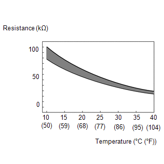
The resistance of the thermistor built into the generator temperature sensor changes in accordance with changes in generator (MG1) temperature. The lower the generator (MG1) temperature, the higher the thermistor resistance. Conversely, the higher the generator (MG1) temperature, the lower the resistance.
| DTC No. | Detection Item | DTC Detection Condition | Trouble Area | MIL | Warning Indicate |
|---|---|---|---|---|---|
| P0A37-260 | Generator Temperature Sensor Circuit Range / Performance | After a long soak, the value of the generator (MG1) temperature sensor is different from the value of the other temperature sensors. (2 trip detection logic) |
| Comes on | Master Warning Light: Comes on |
| P0A3A-258 | Generator Temperature Sensor Circuit Intermittent | Sudden change in generator temperature sensor output or hunting Unusual sudden change in generator temperature sensor output occurs and offset condition continues for a certain period of time, or unusual change in motor temperature sensor output occurs repeatedly. (1 trip detection logic) |
| Comes on | Master Warning Light: Comes on |
| DTC No. | Data List |
|---|---|
| P0A37-260 | Motor Temp No2 |
| P0A3A-258 |
MONITOR DESCRIPTION
If the hybrid vehicle control ECU detects a malfunction of the generator temperature sensor, it will illuminate the MIL and store a DTC.
MONITOR STRATEGY
| Related DTCs | P0A37 (INF 260): Generator Temperature Sensor Circuit Range/Performance P0A3A (INF 258): Generator Temperature Sensor Circuit Intermittent |
| Required sensors/components | Generator temperature sensor |
| Frequency of operation | Continuous |
| Duration | TMC's intellectual property |
| MIL operation | 2 driving cycle: P0A37-260 1 driving cycle: P0A3A-258 |
| Sequence of operation | None |
TYPICAL ENABLING CONDITIONS
| The monitor will run whenever the following DTCs are not stored | TMC's intellectual property |
| Other conditions belong to TMC's intellectual property | - |
TYPICAL MALFUNCTION THRESHOLDS
| TMC's intellectual property | - |
COMPONENT OPERATING RANGE
| Hybrid vehicle control ECU assembly | DTC P0A37 (INF 260) is not detected DTC P0A3A (INF 258) is not detected |
CONFIRMATION DRIVING PATTERN
HINT:
After the repair, clear the DTCs and perform the following procedure to check that DTCs (including pending DTCs) are not output.
- Connect the Techstream to the DLC3.
- Turn the power switch on (IG) and turn the Techstream on.
- Clear the DTCs (even if no DTCs are stored, perform the clear DTC procedure).
- Turn the power switch on (Ready), wait for 10 seconds or more and turn the power switch off.
- Leave the vehicle as is for 5 hours or more and then check that the values of the Data List items "Motor Temp No1", "Motor Temp No2" and "Inverter Coolant Water Temperature" are approximately the same.
- Turn the power switch on (IG) and turn the Techstream on.
- Enter the following menus: Powertrain / Hybrid Control / Trouble Codes.
-
Read the pending DTCs. (DTC P0A37-260)
HINT:
- If a pending DTC is output, the system is malfunctioning.
- If pending DTCs are not output, perform the following steps to check for permanent DTCs.
-
Read the current DTCs. (DTC P0A3A-258)
HINT:
- If a current DTC is output, the system is malfunctioning.
- If a current DTC is not output, perform the following procedure.
- Check that permanent DTCs are cleared. If no permanent DTC is output, the system is normal.
- If the permanent DTCs are not cleared, perform the universal trip, and then check for permanent DTCs again.
WIRING DIAGRAM
Refer to the wiring diagram for DTC P0A38-257.
Click here .gif)
PROCEDURE
| 1. | CHECK CONNECTOR CONNECTION CONDITION (HYBRID VEHICLE CONTROL ECU CONNECTOR) |
Click here
| Result | Proceed to |
|---|---|
| OK | A |
| NG (The connector is not connected securely.) | B |
| NG (The terminals are not making secure contact or are deformed, or water or foreign matter exists in the connector.) | C |
| B | .gif) | CONNECT SECURELY |
| C | | REPAIR OR REPLACE HARNESS OR CONNECTOR |
|
.gif)
| 2. | CHECK HARNESS AND CONNECTOR (NO. 1 ENGINE ROOM RELAY BLOCK - HYBRID VEHICLE CONTROL ECU) |
(a) Disconnect the A60 hybrid vehicle control ECU connector.
| (b) Measure the resistance according to the value(s) in the table below. Standard Resistance:
|
|
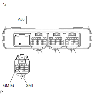
(c) Reconnect the A60 hybrid vehicle control ECU connector.
| NG | | GO TO STEP 7 |
|
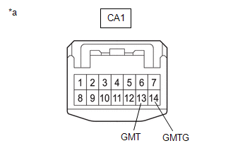
| 3. | CHECK CONNECTOR CONNECTION CONDITION (NO. 1 ENGINE ROOM RELAY BLOCK CA1 CONNECTOR) |
Click here
| Result | Proceed to |
|---|---|
| OK | A |
| NG (The connector is not connected securely.) | B |
| NG (The terminals are not making secure contact or are deformed, or water or foreign matter exists in the connector.) | C |
| B | | CONNECT SECURELY |
| C | | REPAIR OR REPLACE HARNESS OR CONNECTOR |
|
| 4. | CHECK HARNESS AND CONNECTOR (HYBRID VEHICLE CONTROL ECU - NO. 1 ENGINE ROOM RELAY BLOCK) |
(a) Disconnect the CA1 No. 1 engine room relay block connector.
(b) Disconnect the A60 hybrid vehicle control ECU connector.
(c) Measure the resistance according to the value(s) in the table below.
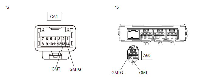
| *a | Front view of wire harness connector (to No. 1 Engine Room Relay Block) | *b | Rear view of wire harness connector (to Hybrid Vehicle Control ECU) |
HINT:
When performing the measurement, lightly jiggle the wire harness up and down and left and right and confirm that the resistance does not fluctuate.
Standard Resistance (Check for Open):
| Tester Connection | Condition | Specified Condition |
|---|---|---|
| CA1-13 (GMT) - A60-26 (GMT) | Power switch off | Below 1 Ω |
| CA1-14 (GMTG) - A60-27 (GMTG) | Power switch off | Below 1 Ω |
Standard Resistance (Check for Short):
| Tester Connection | Condition | Specified Condition |
|---|---|---|
| CA1-13 (GMT) or A60-26 (GMT) - Body ground and other terminals | Power switch off | 10 kΩ or higher |
| CA1-14 (GMTG) or A60-27 (GMTG) - Body ground and other terminals | Power switch off | 10 kΩ or higher |
(d) Reconnect the A60 hybrid vehicle control ECU connector.
(e) Reconnect the CA1 No. 1 engine room relay block connector.
| NG | | REPAIR OR REPLACE HARNESS OR CONNECTOR |
|
| 5. | CHECK CONNECTOR CONNECTION CONDITION (GENERATOR TEMPERATURE SENSOR CONNECTOR) |
Click here
| Result | Proceed to |
|---|---|
| OK | A |
| NG (The connector is not connected securely.) | B |
| NG (The terminals are not making secure contact or are deformed, or water or foreign matter exists in the connector.) | C |
| B | | CONNECT SECURELY |
| C | | REPAIR OR REPLACE HARNESS OR CONNECTOR |
|
| 6. | CHECK HARNESS AND CONNECTOR (NO. 1 ENGINE ROOM RELAY BLOCK - GENERATOR TEMPERATURE SENSOR) |
(a) Disconnect the C41 generator temperature sensor connector.
(b) Disconnect the CA1 No. 1 engine room relay block connector.
(c) Measure the resistance according to the value(s) in the table below.
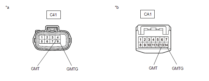
| *a | Front view of wire harness connector (to Generator Temperature Sensor) | *b | Front view of wire harness connector (to No. 1 Engine Room Relay Block) |
HINT:
When performing the measurement, lightly jiggle the wire harness up and down and left and right and confirm that the resistance does not fluctuate.
Standard Resistance (Check for Open):
| Tester Connection | Condition | Specified Condition |
|---|---|---|
| CA1-13 (GMT) - C41-4 (GMT) | Power switch off | Below 1 Ω |
| CA1-14 (GMTG) - C41-8 (GMTG) | Power switch off | Below 1 Ω |
Standard Resistance (Check for Short):
| Tester Connection | Condition | Specified Condition |
|---|---|---|
| CA1-13 (GMT) or C41-4 (GMT) - Body ground and other terminals | Power switch off | 10 kΩ or higher |
| CA1-14 (GMTG) or C41-8 (GMTG) - Body ground and other terminals | Power switch off | 10 kΩ or higher |
(d) Reconnect the CA1 No. 1 engine room relay block connector.
(e) Reconnect the C41 generator temperature sensor connector.
| OK | | REPLACE HYBRID VEHICLE TRANSAXLE ASSEMBLY |
| NG | | REPAIR OR REPLACE HARNESS OR CONNECTOR |
| 7. | INSPECT HYBRID VEHICLE TRANSAXLE ASSEMBLY (GENERATOR TEMPERATURE SENSOR) |
(a) Disconnect the CA1 No. 1 engine room relay block connector.
| (b) Measure the resistance according to the value(s) in the table below. Standard Resistance:
|
|
(c) Reconnect the CA1 No. 1 engine room relay block connector.
| OK | | REPAIR OR REPLACE HARNESS OR CONNECTOR (HYBRID VEHICLE CONTROL ECU - NO. 1 ENGINE ROOM RELAY BLOCK) |
|
| 8. | INSPECT HYBRID VEHICLE TRANSAXLE ASSEMBLY (GENERATOR TEMPERATURE SENSOR) |
Click here
| OK | | REPAIR OR REPLACE HARNESS OR CONNECTOR (NO. 1 ENGINE ROOM RELAY BLOCK - GENERATOR TEMPERATURE SENSOR) |
| NG | | REPLACE HYBRID VEHICLE TRANSAXLE ASSEMBLY |
READ NEXT:
 Generator Temperature Sensor Circuit Low (P0A38-257,P0A39-259)
DESCRIPTION Refer to the description for DTC P0A37-260. Click here DTC No. Detection Item DTC Detection Condition Trouble Area MIL Warning Indicate P0A38-257 Generator Temperature
Drive Motor "A" Position Sensor Circuit (P0A3F-243,P0A40-500,P0A41-245)
DTC SUMMARY MALFUNCTION DESCRIPTION These DTCs indicate the resolver output signal is abnormal. The cause of this malfunction may be one of the following: Area Main Malfunction Description Step
Drive Motor "A" Position Sensor Circuit Range / Performance (P0A40-504)
DTC SUMMARY MALFUNCTION DESCRIPTION This DTC indicates that an overvoltage in the inverter has occurred. The cause of this malfunction may be one of the following: Area Main Malfunction Descripti
SEE MORE:
No Sound can be Heard from Speakers
PROCEDURE 1. CHECK AUDIO SETTINGS (a) In sound output setting mode, set volume, fader and balance to the initial values and check that the sound is normal. OK: Audio system returns to normal. HINT: Sound quality adjustment measures vary according to the type of amplifier. OK END
Steering Angle Sensor Failure (C1626)
DESCRIPTION This DTC is stored if the rear television camera assembly receives a signal via CAN communication from the steering sensor that indicates an internal malfunction. DTC No. Detection Item DTC Detection Condition Trouble Area C1626 Steering Angle Sensor Failure A fail flag
