
Lexus NX: Components
Lexus NX Service Manual / Engine & Hybrid System / 2ar-fxe (emission Control) / Egr Valve / Components
COMPONENTS
ILLUSTRATION
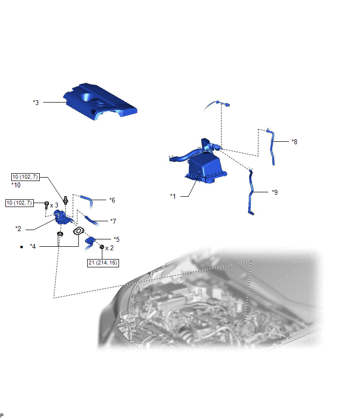
| *1 | AIR CLEANER CAP AND HOSE | *2 | EGR VALVE ASSEMBLY |
| *3 | NO. 1 ENGINE COVER SUB-ASSEMBLY | *4 | GASKET |
| *5 | NO. 1 EGR PIPE | *6 | NO. 1 WATER BY-PASS HOSE |
| *7 | NO. 2 WATER BY-PASS HOSE | *8 | FUEL VAPOR FEED HOSE |
| *9 | NO. 2 FUEL VAPOR FEED HOSE | *10 | ENGINE COVER JOINT |
.png) | N*m (kgf*cm, ft.*lbf): Specified torque | ● | Non-reusable part |
READ NEXT:
 Removal
REMOVAL PROCEDURE 1. DRAIN ENGINE COOLANT Click here 2. REMOVE NO. 1 ENGINE COVER SUB-ASSEMBLY Click here 3. REMOVE AIR CLEANER CAP AND HOSE Click here 4. REMOVE EGR VALVE ASSEMBLY (a) Discon
Inspection
INSPECTION PROCEDURE 1. INSPECT EGR VALVE ASSEMBLY (a) Measure the resistance. (1) Measure the resistance according to the value(s) in the table below. Standard Resistance: Tester Connection
Installation
INSTALLATION CAUTION / NOTICE / HINT HINT: Perform "Inspection After Repair" after replacing the EGR valve assembly. Click here PROCEDURE 1. INSTALL EGR VALVE ASSEMBLY HINT: Perform "Inspection Afte
SEE MORE:
Drive Motor "A" Phase V Current Sensor Circuit Range / Performance (P0BEA-290,...,P1C6E-502)
DTC SUMMARY MALFUNCTION DESCRIPTION These DTCs indicate the current sensor value is abnormal. The cause of this malfunction may be one of the following: Internal inverter malfunction
Inverter with converter assembly internal circuit malfunction
Inverter low-voltage circuit malfunction
The c
Removal
REMOVAL CAUTION / NOTICE / HINT w/ Blind Spot Monitor System: HINT: If the bumper is damaged, there is a possibility that the installation area of the blind spot monitor sensor may be deformed and the blind spot monitor system may not be operating correctly, so visually inspect the blind spot monito
© 2016-2026 Copyright www.lexunx.com
