
Lexus NX: Removal
REMOVAL
PROCEDURE
1. DRAIN ENGINE COOLANT
Click here .gif)
2. REMOVE NO. 1 ENGINE COVER SUB-ASSEMBLY
Click here
3. REMOVE AIR CLEANER CAP AND HOSE
Click here
4. REMOVE EGR VALVE ASSEMBLY
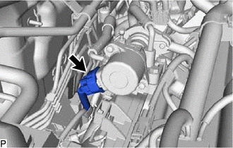
| (a) Disconnect the connector from the EGR valve assembly. |
|
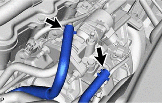
| (b) Slide the 2 clamps and disconnect the No. 1 water by-pass hose and No. 2 water by-pass hose from the EGR valve assembly. |
|
| (c) Using a 10 mm deep socket wrench, remove the engine cover joint from the EGR valve assembly. |
|
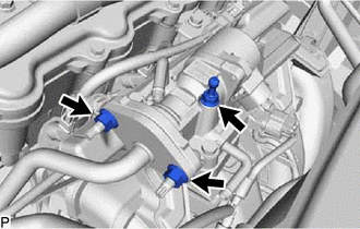
(d) Using a 12 mm deep socket wrench, remove the 2 nuts and disconnect the No. 1 EGR pipe from the EGR valve assembly.
| (e) Remove the 3 bolts and EGR valve assembly from the intake manifold. |
|
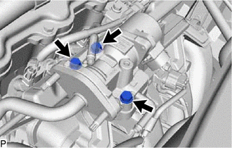
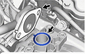
| (f) Remove the 2 gaskets from the No. 1 EGR pipe and intake manifold. |
|
READ NEXT:
 Inspection
INSPECTION PROCEDURE 1. INSPECT EGR VALVE ASSEMBLY (a) Measure the resistance. (1) Measure the resistance according to the value(s) in the table below. Standard Resistance: Tester Connection
Installation
INSTALLATION CAUTION / NOTICE / HINT HINT: Perform "Inspection After Repair" after replacing the EGR valve assembly. Click here PROCEDURE 1. INSTALL EGR VALVE ASSEMBLY HINT: Perform "Inspection Afte
SEE MORE:
Disassembly
DISASSEMBLY CAUTION / NOTICE / HINT NOTICE:
When using a vise, place aluminum plates between the part and vise.
When using a vise, do not overtighten it.
HINT:
Use the same procedure for the RH and LH sides.
The procedure listed below is for the LH side.
PROCEDURE 1. DISCONNECT REAR
Removal
REMOVAL PROCEDURE 1. DISCONNECT INTAKE MANIFOLD Click here 2. DISCONNECT FUEL TUBE SUB-ASSEMBLY (a) Remove the No. 1 fuel pipe clamp from the fuel tube sub-assembly. Click here (b) Disconnect the fuel tube sub-assembly from the fuel pipe. Click here 3. REMOVE FUEL DELIVERY P
© 2016-2026 Copyright www.lexunx.com
