Lexus NX: Folding Motor Circuit
DESCRIPTION
The fold seat control ECU receives switch operation signals from the No. 1 and No. 2 fold seat switches and activates the power seat motors. At this time, the Hall IC detects the actuation of the seat cushion and sends a seat cushion actuation signal to the fold seat control ECU. The fold seat control ECU uses signals from the Hall IC to detect if an object is caught or if any other abnormal condition has occurred.
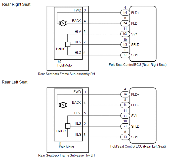
WIRING DIAGRAM
PROCEDURE
| 1. | INSPECT REAR SEATBACK FRAME SUB-ASSEMBLY (FOLD MOTOR) |
(a) Remove the rear seatback frame sub-assembly.
Click here .gif)
(b) Inspect the rear seatback frame sub-assembly.
Click here
| NG | .gif) | REPLACE REAR SEATBACK FRAME SUB-ASSEMBLY |
|
.gif)
| 2. | CHECK HARNESS AND CONNECTOR (FOLD SEAT CONTROL ECU - REAR SEATBACK FRAME SUB-ASSEMBLY) |
(a) Rear Right Seat:
(1) Disconnect the h3 and h4 fold seat control ECU (rear right seat) connectors.
(2) Disconnect the h2 rear seatback frame sub-assembly RH connector.
(b) Rear Left Seat:
(1) Disconnect the i3 and i4 fold seat control ECU (rear left seat) connectors.
(2) Disconnect the i1 rear seatback frame sub-assembly LH connector.
(c) Measure the resistance according to the value(s) in the table below.
Standard Resistance:
Rear Right Seat
| Tester Connection | Condition | Specified Condition |
|---|---|---|
| h3-11 (SV1) - h2-5 (HLV) | Always | Below 1 Ω |
| h3-11 (SV1) or h2-5 (HLV) - Body ground | Always | 10 kΩ or higher |
| h3-10 (SFLD) - h2-2 (HLS) | Always | Below 1 Ω |
| h3-10 (SFLD) or h2-2 (HLS) - Body ground | Always | 10 kΩ or higher |
| h3-8 (SG1) - h2-6 (HLG) | Always | Below 1 Ω |
| h3-8 (SG1) or h2-6 (HLG) - Body ground | Always | 10 kΩ or higher |
| h4-4 (FLD+) - h2-3 (FWD) | Always | Below 1 Ω |
| h4-4 (FLD+) or h2-3 (FWD) - Body ground | Always | 10 kΩ or higher |
| h4-8 (FLD-) - h2-4 (BACK) | Always | Below 1 Ω |
| h4-8 (FLD-) or h2-4 (BACK) - Body ground | Always | 10 kΩ or higher |
Rear Left Seat
| Tester Connection | Condition | Specified Condition |
|---|---|---|
| i3-11 (SV1) - i1-5 (HLV) | Always | Below 1 Ω |
| i3-11 (SV1) or i1-5 (HLV) - Body ground | Always | 10 kΩ or higher |
| i3-10 (SFLD) - i2-2 (HLS) | Always | Below 1 Ω |
| i3-10 (SFLD) or i2-2 (HLS) - Body ground | Always | 10 kΩ or higher |
| i3-8 (SG1) - i1-6 (HLG) | Always | Below 1 Ω |
| i3-8 (SG1) or i1-6 (HLG) - Body ground | Always | 10 kΩ or higher |
| i4-4 (FLD+) - i1-3 (FWD) | Always | Below 1 Ω |
| i4-4 (FLD+) or i1-3 (FWD) - Body ground | Always | 10 kΩ or higher |
| i4-8 (FLD-) - i1-4 (BACK) | Always | Below 1 Ω |
| i4-8 (FLD-) or i1-4 (BACK) - Body ground | Always | 10 kΩ or higher |
| NG | | REPAIR OR REPLACE HARNESS OR CONNECTOR |
|
| 3. | CHECK REAR SEATBACK FRAME SUB-ASSEMBLY (SENSOR) |
(a) Temporarily replace the rear seatback frame sub-assembly with a new or known good one.
Click here
(b) Check the rear power seat system.
| OK | | END (REAR SEATBACK FRAME SUB-ASSEMBLY WAS DEFECTIVE) |
| NG | | REPLACE FOLD SEAT CONTROL ECU |
READ NEXT:
 Reclining Motor Circuit
DESCRIPTION The fold seat control ECU receives switch operation signals from the No. 1 and No. 2 fold seat switches and rear power seat switch and activates the power seat motors. At this time, the Ha
Rear Power Seat Switch Circuit
DESCRIPTION When the rear power seat switch is operated, a recline signal is sent to the fold seat control ECU. The ECU activates the power seat motor based on the signal from the rear power seat swit
SEE MORE:
Removal
REMOVAL PROCEDURE 1. REMOVE NO. 1 ENGINE UNDER COVER ASSEMBLY Click here 2. DRAIN COOLANT (for Inverter Coolant) Click here 3. REMOVE UPPER RADIATOR SUPPORT SUB-ASSEMBLY Click here 4. DISCONNECT NO. 2 INVERTER COOLING HOSE ASSEMBLY Click here 5. REMOVE WATER PUMP WITH MOTOR (a) Disconn
MIL Circuit
DESCRIPTION The Malfunction Indicator Lamp (MIL) is used to indicate vehicle malfunctions detected by the ECM. The MIL operation can be checked visually. When the power switch is turned on (IG), the MIL should be illuminated and should then turn off after the power switch on (READY). If the MIL rema
