Lexus NX: Front Acceleration Sensor RH Malfunction (C1715-C1717,C1796-C1798)
DESCRIPTION
The acceleration sensor assembly (up and down G sensor) detects the upward and downward acceleration of the vehicle and outputs it as a voltage to the absorber control ECU.
Up and down G sensors are installed in 3 locations: 1) the driver side instrument panel, 2) the passenger side instrument panel, and 3) the absorber control ECU.
Each up and down G sensor independently detects the upward and downward acceleration of the vehicle.
During a test mode inspection, the absorber control ECU reads the fluctuations in each sensor signal.
When a sensor signal does not fluctuate, test mode DTCs C1796, C1797 and C1798 remain stored.
| DTC No. | Detection Item | DTC Detection Condition | Trouble Area | Warning Indicate |
|---|---|---|---|---|
| C1715 | Front Acceleration Sensor RH Malfunction | Either condition is met:
|
| Does not come on |
| C1716 | Front Acceleration Sensor LH Malfunction | Either condition is met:
|
| Does not come on |
| C1717 | Rear Acceleration Sensor Malfunction | Either condition is met:
| Absorber control ECU (built into rear acceleration sensor) | Does not come on |
| C1796 | Front Acceleration Sensor RH Malfunction (Test Mode DTC) | With the vehicle stationary on a level surface, an acceleration sensor value that is within -1.96 to 1.96 m/s2 is not received from the front acceleration sensor assembly RH for 1 second or more. |
| Test mode |
| C1797 | Front Acceleration Sensor LH Malfunction (Test Mode DTC) | With the vehicle stationary on a level surface, an acceleration sensor value that is within -1.96 to 1.96 m/s2 is not received from the front acceleration sensor assembly LH for 1 second or more. |
| Test mode |
| C1798 | Rear Acceleration Sensor Malfunction (Test Mode DTC) | With the vehicle stationary on a level surface, an acceleration sensor value that is within -1.96 to 1.96 m/s2 is not received from the rear acceleration sensor for 1 second or more. | Absorber control ECU (built into rear acceleration sensor) | Test mode |
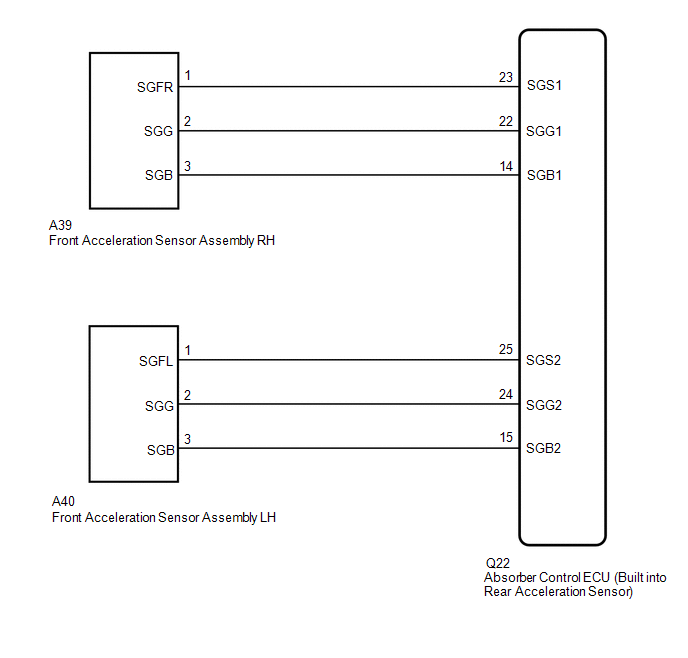
WIRING DIAGRAM
CAUTION / NOTICE / HINT
NOTICE:
- Before performing troubleshooting, inspect the connectors of related circuits.
-
If DTC C1782 (Power Source Voltage Malfunction) is output at the same time, perform troubleshooting for C1782 first.
Click here
.gif)
-
Before replacing the absorber control ECU, perform all of the following again: 1) symptom simulation ; 2) DTC inspection ; and 3) Techstream inspection (ECU Data List or Active Test ). If no malfunctions are found in other areas, replace the absorber control ECU.
-
When the absorber control ECU is replaced, switch to test mode and check that all test mode DTCs are cleared when their respective deletion conditions are met.
Click here
PROCEDURE
| 1. | READ VALUE USING TECHSTREAM ((UP & DOWN) G SENSOR) |
(a) Turn the power switch off.
(b) Connect the Techstream to the DLC3.
(c) Turn the power switch on (IG).
(d) Turn the Techstream on.
(e) Enter the following menus: Chassis / Air suspension / Data List.
Chassis > Air suspension > Data List| Tester Display | Measurement Item | Range | Normal Condition | Diagnostic Note |
|---|---|---|---|---|
| (Up&Down)G Sensor FR | Front acceleration sensor RH (up and down) | Min.: -1045.29 m/s2 Max.: 1045.26 m/s2 | -0.98 to 0.98 m/s2 when stationary | The value changes when the vehicle (front RH) is bounced. |
| (Up&Down)G Sensor FL | Front acceleration sensor LH (up and down) | Min.: -1045.29 m/s2 Max.: 1045.26 m/s2 | -0.98 to 0.98 m/s2 when stationary | The value changes when the vehicle (front LH) is bounced. |
| (Up&Down)G Sensor Rear | Rear acceleration sensor (up and down) | Min.: -1045.29 m/s2 Max.: 1045.26 m/s2 | -0.98 to 0.98 m/s2 when stationary | The value changes when the vehicle (rear) is bounced. |
| Tester Display |
|---|
| (Up&Down)G Sensor FR |
| (Up&Down)G Sensor FL |
| (Up&Down)G Sensor Rear |
OK:
Acceleration value changes.
| Result | Proceed to |
|---|---|
| OK | A |
| NG (rear) | B |
| NG (front RH or front LH) | C |
| B | .gif) | REPLACE ABSORBER CONTROL ECU |
| C | | GO TO STEP 3 |
|
.gif)
| 2. | RECONFIRM DTC |
(a) Clear the DTCs.
Click here
(b) Turn the power switch off.
(c) Check for DTCs.
Click here
| Result | Proceed to |
|---|---|
| DTC is output (front RH or front LH) | A |
| DTC is output (rear) | B |
| DTC is not output | C |
| B | | REPLACE ABSORBER CONTROL ECU |
| C | | USE SIMULATION METHOD TO CHECK |
|
| 3. | INSPECT ACCELERATION SENSOR ASSEMBLY (FRONT RH OR FRONT LH) |
(a) Turn the power switch off.
(b) Remove the front acceleration sensor assembly RH or front acceleration sensor assembly LH.
Click here
NOTICE:
Do not drop the acceleration sensor. If it is dropped, replace it with a new one.
(c) Inspect the front acceleration sensor assembly RH or front acceleration sensor assembly LH.
Click here
| Result | Proceed to |
|---|---|
| OK | A |
| Front acceleration sensor assembly RH malfunction | B |
| Front acceleration sensor assembly LH malfunction | C |
| B | | REPLACE FRONT ACCELERATION SENSOR ASSEMBLY RH |
| C | | REPLACE FRONT ACCELERATION SENSOR ASSEMBLY LH |
|
| 4. | CHECK HARNESS AND CONNECTOR (FRONT ACCELERATION SENSOR ASSEMBLY - ABSORBER CONTROL ECU) |
(a) Check the front acceleration sensor assembly RH harness and connector (when DTC C1715 or C1796 is output).
(1) Disconnect the Q22 absorber control ECU connector.
(2) Disconnect the A39 front acceleration sensor assembly RH connector.
(3) Measure the resistance according to the value(s) in the table below.
Standard Resistance:
| Tester Connection | Condition | Specified Condition |
|---|---|---|
| A39-1 (SGFR) - Q22-23 (SGS1) | Always | Below 1 Ω |
| A39-2 (SGG) - Q22-22 (SGG1) | Always | Below 1 Ω |
| A39-3 (SGB) - Q22-14 (SGB1) | Always | Below 1 Ω |
| A39-1 (SGFR) or Q22-23 (SGS1) - Body ground | Always | 10 kΩ or higher |
| A39-2 (SGG) or Q22-22 (SGG1) - Body ground | Always | 10 kΩ or higher |
| A39-3 (SGB) or Q22-14 (SGB1) - Body ground | Always | 10 kΩ or higher |
(b) Check the front acceleration sensor assembly LH harness and connector (when DTC C1716 or C1797 is output).
(1) Disconnect the Q22 absorber control ECU connector.
(2) Disconnect the A40 front acceleration sensor assembly LH connector.
(3) Measure the resistance according to the value(s) in the table below.
Standard Resistance:
| Tester Connection | Condition | Specified Condition |
|---|---|---|
| A40-1 (SGFL) - Q22-25 (SGS2) | Always | Below 1 Ω |
| A40-2 (SGG) - Q22-24 (SGG2) | Always | Below 1 Ω |
| A40-3 (SGB) - Q22-15 (SGB2) | Always | Below 1 Ω |
| A40-1 (SGFL) or Q22-25 (SGS2) - Body ground | Always | 10 kΩ or higher |
| A40-2 (SGG) or Q22-24 (SGG2) - Body ground | Always | 10 kΩ or higher |
| A40-3 (SGB) or Q22-15 (SGB2) - Body ground | Always | 10 kΩ or higher |
| OK | | REPLACE ABSORBER CONTROL ECU |
| NG | | REPAIR OR REPLACE HARNESS OR CONNECTOR |
READ NEXT:
 Front Damping Force Control Actuator RH Circuit Malfunction (C1731-C1734)
DESCRIPTION The absorber control actuator changes the damping force depending on absorber control ECU signals. DTC No. Detection Item DTC Detection Condition Trouble Area Warning Indicate
Suspension Control ECU Malfunction (C1781)
DESCRIPTION If a malfunction in the absorber control ECU is detected, DTC C1781 is stored. DTC No. Detection Item DTC Detection Condition Trouble Area Warning Indicate C1781 Suspensio
Power Source Voltage Malfunction (C1782)
DESCRIPTION DTC No. Detection Item DTC Detection Condition Trouble Area Warning Indicate C1782 Power Source Voltage Malfunction While the power switch is on (IG), the voltage at ter
SEE MORE:
Problem Symptoms Table
PROBLEM SYMPTOMS TABLE HINT:
Use the table below to help determine the cause of problem symptoms. If multiple suspected areas are listed, the potential causes of the symptoms are listed in order of probability in the "Suspected Area" column of the table. Check each symptom by checking the suspect
Interior Light Auto Cut Circuit
DESCRIPTION The main body ECU (multiplex network body ECU) controls the DOME CUT relay. WIRING DIAGRAM CAUTION / NOTICE / HINT NOTICE:
Inspect the fuses for circuits related to this system before performing the following procedure.
Recognition code registration is necessary when replacing the
