Lexus NX: Front Camera Feedback Malfunction (C1681)
DESCRIPTION
This DTC is stored if the parking assist ECU judges as a result of its self check that a synchronization problem is occurring in the image signal sent from the front television camera assembly to the parking assist ECU.
| DTC No. | Detection Item | DTC Detection Condition | Trouble Area |
|---|---|---|---|
| C1681 | Front Camera Feedback Malfunction | Front television camera power supply failure |
|
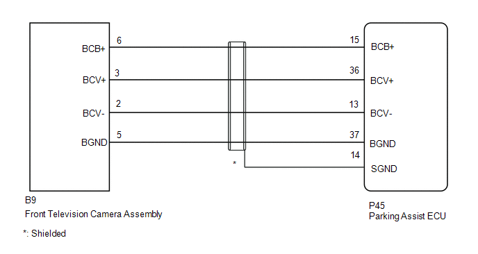
WIRING DIAGRAM
CAUTION / NOTICE / HINT
NOTICE:
-
When "!" mark is displayed on the multi-display assembly after the cable is disconnected from the negative (-) auxiliary battery terminal, correct the steering angle neutral point.
Click here
.gif)
-
Depending on the parts that are replaced or operations that are performed during vehicle inspection or maintenance, calibration of other systems as well as panoramic view monitor system may be needed.
Click here
PROCEDURE
| 1. | CHECK HARNESS AND CONNECTOR (PARKING ASSIST ECU - FRONT TELEVISION CAMERA ASSEMBLY) |
(a) Disconnect the P45 parking assist ECU connector.
(b) Disconnect the B9 front television camera assembly connector.
(c) Measure the resistance according to the value(s) in the table below.
Standard Resistance:
| Tester Connection | Condition | Specified Condition |
|---|---|---|
| P45-15 (BCB+) - B9-6 (BCB+) | Always | Below 1 Ω |
| P45-36 (BCV+) - B9-3 (BCV+) | Always | Below 1 Ω |
| P45-13 (BCV-) - B9-2 (BCV-) | Always | Below 1 Ω |
| P45-37 (BGND) - B9-5 (BGND) | Always | Below 1 Ω |
| P45-14 (SGND) - Body ground | Always | Below 1 Ω |
| P45-15 (BCB+) or B9-6 (BCB+) - Body ground | Always | 10 kΩ or higher |
| P45-36 (BCV+) or B9-3 (BCV+) - Body ground | Always | 10 kΩ or higher |
| P45-13 (BCV-) or B9-2 (BCV-) - Body ground | Always | 10 kΩ or higher |
| P45-37 (BGND) or B9-5 (BGND) - Body ground | Always | 10 kΩ or higher |
| NG | .gif) | REPAIR OR REPLACE HARNESS OR CONNECTOR |
|
.gif)
| 2. | CHECK PARKING ASSIST ECU (BCV-, BGND) |
| (a) Disconnect the parking assist ECU connector. |
|
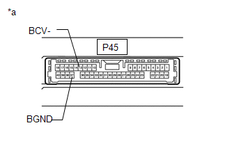
(b) Measure the resistance according to the value(s) in the table below.
Standard Resistance:
| Tester Connection | Condition | Specified Condition |
|---|---|---|
| 37 (BGND) - Body ground | Always | Below 1 Ω |
| 13 (BCV-) - Body ground | Always | Below 1 Ω |
| NG | | REPLACE PARKING ASSIST ECU |
|
| 3. | CHECK PARKING ASSIST ECU (BCB+, BGND) |
| (a) Disconnect the front television camera assembly connector. |
|
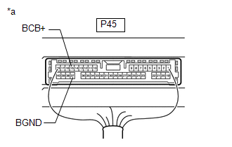
(b) Measure the voltage according to the value(s) in the table below.
Standard Voltage:
| Tester Connection | Switch Condition | Specified Condition |
|---|---|---|
| P45-15 (BCB+) - P45-37 (BGND) | Power switch on (IG) | 5.5 to 7.05 V |
| P45-15 (BCB+) - P45-37 (BGND) | Power switch off | Below 1 V |
| NG | | REPLACE PARKING ASSIST ECU |
|
| 4. | CHECK FRONT TELEVISION CAMERA ASSEMBLY (BCV+, BGND) |
(a) Remove the parking assist ECU with the connector still connected.
(b) Using an oscilloscope, check the waveform of the front television camera assembly.
HINT:
A waterproof connector is used for the front television camera assembly. Therefore, inspect the waveform at the parking assist ECU with the connector connected.
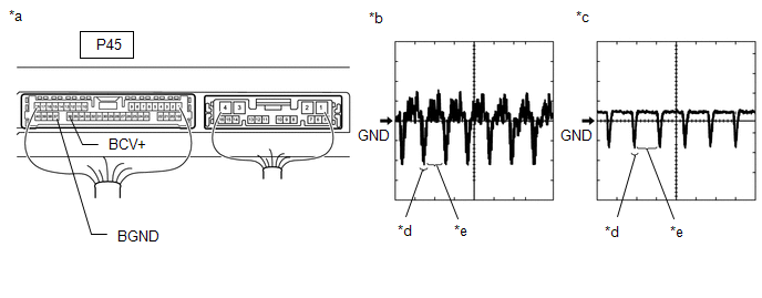
| *a | Component with harness connected (Parking Assist ECU) | *b | Waveform 1 (camera lens not covered, displaying an image) |
| *c | Waveform 2 (camera lens covered, blacking out the screen) | *d | Synchronization Signal |
| *e | Video Waveform | - | - |
HINT:
- The video waveform changes according to the image sent by the front television camera assembly.
- The video waveform is constantly output when the power switch is on (ACC).
| Item | Content |
|---|---|
| Terminal No. (Symbol) | P45-36 (BCV+) - P45-37 (BGND) |
| Tool Setting | 200 mV/DIV., 50 μsec./DIV. |
| Condition | Power switch on (IG), panoramic view monitor switch on |
OK:
Waveform is similar to that shown in the illustration.
| OK | | REPLACE PARKING ASSIST ECU |
| NG | | REPLACE FRONT TELEVISION CAMERA ASSEMBLY |
READ NEXT:
 Front Camera Current Malfunction (C1682)
DESCRIPTION This DTC is stored if the parking assist ECU judges as a result of its self check that there is a problem with the current supplied from the front television camera assembly connected to t
Side Camera Feedback Malfunction (C1683)
DESCRIPTION This DTC is stored if the parking assist ECU judges as a result of its self check that a synchronization problem is occurring in the image signal sent from the passenger side television ca
Side Camera Current Malfunction (C1684)
DESCRIPTION This DTC is stored if the parking assist ECU judges as a result of its self check that a synchronization problem is occurring in the image signal sent from the passenger side television ca
SEE MORE:
Mass Air Flow Meter
ComponentsCOMPONENTS ILLUSTRATION *1 MASS AIR FLOW METER SUB-ASSEMBLY - - On-vehicle InspectionON-VEHICLE INSPECTION CAUTION / NOTICE / HINT NOTICE:
Perform the mass air flow meter sub-assembly inspection according to the procedures below.
Only replace the mass air flow meter sub
Display does not Dim when Light Control Switch is Turned ON
DESCRIPTION If the navigation system is turned on with the light control switch in the tail or head position, before AVC-LAN communication is established, the multi-display assembly dims according to the illumination signal received via a direct line. After AVC-LAN communication is established, the
