Lexus NX: Front Sensor Communication Malfunction (C1AEC)
DESCRIPTION
This DTC is stored when there is an open or short circuit in the communication line between the front sensors and the ECU, or when there is a malfunction in a front sensor.
| DTC No. | Detection Item | DTC Detection Condition | Trouble Area |
|---|---|---|---|
| C1AEC | Front Sensor Communication Malfunction | An open or short circuit in the communication line between the front sensors and ECU or a malfunction in a front sensor during initialization mode after the power switch is turned on (IG). |
|
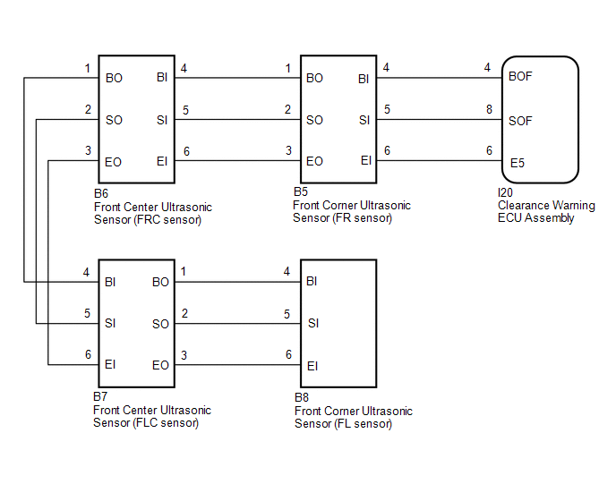
WIRING DIAGRAM
PROCEDURE
| 1. | INITIALIZE FRONT CORNER ULTRASONIC SENSOR AND FRONT CENTER ULTRASONIC SENSOR |
(a) Initialize the front corner ultrasonic sensor (FL and FR sensor) and front center ultrasonic sensor (FLC and FRC sensor).
Click here .gif)
|
.gif)
| 2. | CHECK DTC OUTPUT (C1AEC) |
(a) Check for DTCs.
Click here
(b) Clear the DTCs.
Click here
(c) Recheck for DTCs.
Click here
| Result | Proceed to |
|---|---|
| No DTCs are output | A |
| DTC C1AEC is output | B |
| A | .gif) | USE SIMULATION METHOD TO CHECK |
|
| 3. | CHECK HARNESS AND CONNECTOR (CLEARANCE WARNING ECU ASSEMBLY - FRONT CORNER ULTRASONIC SENSOR [FR SENSOR]) |
(a) Disconnect the I20 clearance warning ECU assembly connector.
(b) Disconnect the B5 front corner ultrasonic sensor (FR sensor) connector.
(c) Measure the resistance according to the value(s) in the table below.
Standard Resistance:
| Tester Connection | Condition | Specified Condition |
|---|---|---|
| I20-4 (BOF) - B5-4 (BI) | Always | Below 1 Ω |
| I20-8 (SOF) - B5-5 (SI) | Always | Below 1 Ω |
| I20-6 (E5) - B5-6 (EI) | Always | Below 1 Ω |
| I20-4 (BOF) or B5-4 (BI) - Body ground | Always | 10 kΩ or higher |
| I20-8 (SOF) or B5-5 (SI) - Body ground | Always | 10 kΩ or higher |
| I20-6 (E5) or B5-6 (EI) - Body ground | Always | 10 kΩ or higher |
| NG | | REPAIR OR REPLACE HARNESS OR CONNECTOR |
|
| 4. | CHECK HARNESS AND CONNECTOR (FRONT CORNER ULTRASONIC SENSOR [FR SENSOR] - FRONT CENTER ULTRASONIC SENSOR [FRC SENSOR]) |
(a) Disconnect the B5 front corner ultrasonic sensor (FR sensor) connector.
(b) Disconnect the B6 front center ultrasonic sensor (FRC sensor) connector.
(c) Measure the resistance according to the value(s) in the table below.
Standard Resistance:
| Tester Connection | Condition | Specified Condition |
|---|---|---|
| B5-1 (BO) - B6-4 (BI) | Always | Below 1 Ω |
| B5-2 (SO) - B6-5 (SI) | Always | Below 1 Ω |
| B5-3 (EO) - B6-6 (EI) | Always | Below 1 Ω |
| B5-1 (BO) or B6-4 (BI) - Body ground | Always | 10 kΩ or higher |
| B5-2 (SO) or B6-5 (SI) - Body ground | Always | 10 kΩ or higher |
| B5-3 (EO) or B6-6 (EI) - Body ground | Always | 10 kΩ or higher |
| NG | | REPAIR OR REPLACE HARNESS OR CONNECTOR |
|
| 5. | CHECK HARNESS AND CONNECTOR (FRONT CENTER ULTRASONIC SENSOR [FRC SENSOR] - FRONT CENTER ULTRASONIC SENSOR [FLC SENSOR]) |
(a) Disconnect the B6 front center ultrasonic sensor (FRC sensor) connector.
(b) Disconnect the B7 front center ultrasonic sensor (FLC sensor) connector.
(c) Measure the resistance according to the value(s) in the table below.
Standard Resistance:
| Tester Connection | Condition | Specified Condition |
|---|---|---|
| B6-1 (BO) - B7-4 (BI) | Always | Below 1 Ω |
| B6-2 (SO) - B7-5 (SI) | Always | Below 1 Ω |
| B6-3 (EO) - B7-6 (EI) | Always | Below 1 Ω |
| B6-1 (BO) or B7-4 (BI) - Body ground | Always | 10 kΩ or higher |
| B6-2 (SO) or B7-5 (SI) - Body ground | Always | 10 kΩ or higher |
| B6-3 (EO) or B7-6 (EI) - Body ground | Always | 10 kΩ or higher |
| NG | | REPAIR OR REPLACE HARNESS OR CONNECTOR |
|
| 6. | CHECK HARNESS AND CONNECTOR (FRONT CENTER ULTRASONIC SENSOR [FLC SENSOR] - FRONT CORNER ULTRASONIC SENSOR [FL SENSOR]) |
(a) Disconnect the B7 front center ultrasonic sensor (FLC sensor) connector.
(b) Disconnect the B8 front corner ultrasonic sensor (FL sensor) connector.
(c) Measure the resistance according to the value(s) in the table below.
Standard Resistance:
| Tester Connection | Condition | Specified Condition |
|---|---|---|
| B7-1 (BO) - B8-4 (BI) | Always | Below 1 Ω |
| B7-2 (SO) - B8-5 (SI) | Always | Below 1 Ω |
| B7-3 (EO) - B8-6 (EI) | Always | Below 1 Ω |
| B7-1 (BO) or B8-4 (BI) - Body ground | Always | 10 kΩ or higher |
| B7-2 (SO) or B8-5 (SI) - Body ground | Always | 10 kΩ or higher |
| B7-3 (EO) or B8-6 (EI) - Body ground | Always | 10 kΩ or higher |
| NG | | REPAIR OR REPLACE HARNESS OR CONNECTOR |
|
| 7. | INSPECT FRONT CORNER ULTRASONIC SENSOR (FL SENSOR) |
(a) Remove the front corner ultrasonic sensor (FL sensor).
Click here
(b) Inspect the front corner ultrasonic sensor (FL sensor).
Click here
| NG | | REPLACE FRONT CORNER ULTRASONIC SENSOR (FL SENSOR) |
|
| 8. | INSPECT FRONT CENTER ULTRASONIC SENSOR (FLC SENSOR) |
(a) Remove the front center ultrasonic sensor (FLC sensor).
Click here
(b) Inspect the front center ultrasonic sensor (FLC sensor).
Click here
| NG | | REPLACE FRONT CENTER ULTRASONIC SENSOR (FLC SENSOR) |
|
| 9. | INSPECT FRONT CENTER ULTRASONIC SENSOR (FRC SENSOR) |
(a) Remove the front center ultrasonic sensor (FRC sensor).
Click here
(b) Inspect the front center ultrasonic sensor (FRC sensor).
Click here
| NG | | REPLACE FRONT CENTER ULTRASONIC SENSOR (FRC SENSOR) |
|
| 10. | INSPECT FRONT CORNER ULTRASONIC SENSOR (FR SENSOR) |
(a) Remove the front corner ultrasonic sensor (FR sensor).
Click here
(b) Inspect the front corner ultrasonic sensor (FR sensor).
Click here
| NG | | REPLACE FRONT CORNER ULTRASONIC SENSOR (FR SENSOR) |
|
| 11. | REPLACE FRONT CORNER ULTRASONIC SENSOR (FL SENSOR) |
(a) Replace the front corner ultrasonic sensor (FL sensor) with a known good one.
Click here
HINT:
All of the sensors are interchangeable. To confirm whether a sensor is functioning normally, switch it with a known good sensor from the other end of the vehicle.
|
| 12. | CHECK DTC OUTPUT (C1AEC) |
(a) Clear the DTCs.
Click here
(b) Check for DTCs.
Click here
| Result | Proceed to |
|---|---|
| No DTCs are output | A |
| DTC C1AEC is output | B |
| A | | END (FRONT CORNER ULTRASONIC SENSOR [FL SENSOR] WAS DEFECTIVE) |
|
| 13. | REPLACE FRONT CENTER ULTRASONIC SENSOR (FLC SENSOR) |
(a) Replace the front center ultrasonic sensor (FLC sensor) with a known good one.
Click here
HINT:
All of the sensors are interchangeable. To confirm whether a sensor is functioning normally, switch it with a known good sensor from the other end of the vehicle.
|
| 14. | CHECK DTC OUTPUT (C1AEC) |
(a) Clear the DTCs.
Click here
(b) Check for DTCs.
Click here
| Result | Proceed to |
|---|---|
| No DTCs are output | A |
| DTC C1AEC is output | B |
| A | | END (FRONT CENTER ULTRASONIC SENSOR [FLC SENSOR] WAS DEFECTIVE) |
|
| 15. | REPLACE FRONT CENTER ULTRASONIC SENSOR (FRC SENSOR) |
(a) Replace the front center ultrasonic sensor (FRC sensor) with a known good one.
Click here
HINT:
All of the sensors are interchangeable. To confirm whether a sensor is functioning normally, switch it with a known good sensor from the other end of the vehicle.
|
| 16. | CHECK DTC OUTPUT (C1AEC) |
(a) Clear the DTCs.
Click here
(b) Check for DTCs.
Click here
| Result | Proceed to |
|---|---|
| No DTCs are output | A |
| DTC C1AEC is output | B |
| A | | END (FRONT CENTER ULTRASONIC SENSOR [FRC SENSOR] WAS DEFECTIVE) |
|
| 17. | REPLACE FRONT CORNER ULTRASONIC SENSOR (FR SENSOR) |
(a) Replace the front corner ultrasonic sensor (FR sensor) with a known good one.
Click here
HINT:
All of the sensors are interchangeable. To confirm whether a sensor is functioning normally, switch it with a known good sensor from the other end of the vehicle.
|
| 18. | CHECK DTC OUTPUT (C1AEC) |
(a) Clear the DTCs.
Click here
(b) Check for DTCs.
Click here
| Result | Proceed to |
|---|---|
| No DTCs are output | A |
| DTC C1AEC is output | B |
| A | | END (FRONT CORNER ULTRASONIC SENSOR [FR SENSOR] WAS DEFECTIVE) |
| B | | REPLACE CLEARANCE WARNING ECU ASSEMBLY |
READ NEXT:
 Rear Sensor Communication Malfunction (C1AED)
DESCRIPTION This DTC is stored when there is an open or short circuit in the communication line between the rear sensors and the ECU, or when there is a malfunction in a rear sensor. DTC No. Dete
Control Module Communication Bus "A" Off (U0073,U0155)
DESCRIPTION These DTCs are stored when the clearance warning ECU assembly cannot receive and recognize several signals via the CAN communication line. DTC No. Detection Item DTC Detection Condi
CAN Communication Failure (Message Registry) (U1000)
DESCRIPTION If DTC U1000 is stored frequently, duplicate the conditions that cause the problem symptoms and perform the inspection again even if the DTC is not output when rechecking for DTCs. DTC
SEE MORE:
Parts Location
PARTS LOCATION ILLUSTRATION *A w/ Parking Assist Monitor System *B w/ Panoramic View Monitor System *1 NO. 2 ENGINE ROOM RELAY BLOCK - DCM FUSE (w/ Manual [SOS] Switch) - ECU-B NO.1 FUSE - ECU-B NO.5 FUSE *2 NO. 1 ENGINE ROOM RELAY BLOCK - AMP FUSE - RADIO FUSE - METER NO.1 FUSE
Status Signal Circuit
DESCRIPTION This circuit sends a charging stop signal from the certification ECU (smart key ECU assembly) to the mobile wireless charger cradle assembly. Based on this signal, the wireless charging system stops the charging operation. HINT: The charging frequency of the wireless charging system over
