Lexus NX: Rear Sensor Communication Malfunction (C1AED)
DESCRIPTION
This DTC is stored when there is an open or short circuit in the communication line between the rear sensors and the ECU, or when there is a malfunction in a rear sensor.
| DTC No. | Detection Item | DTC Detection Condition | Trouble Area |
|---|---|---|---|
| C1AED | Rear Sensor Communication Malfunction | An open or short circuit in the communication line between the rear sensors and ECU or a malfunction in a rear sensor during initialization mode after the power switch is turned on (IG). |
|
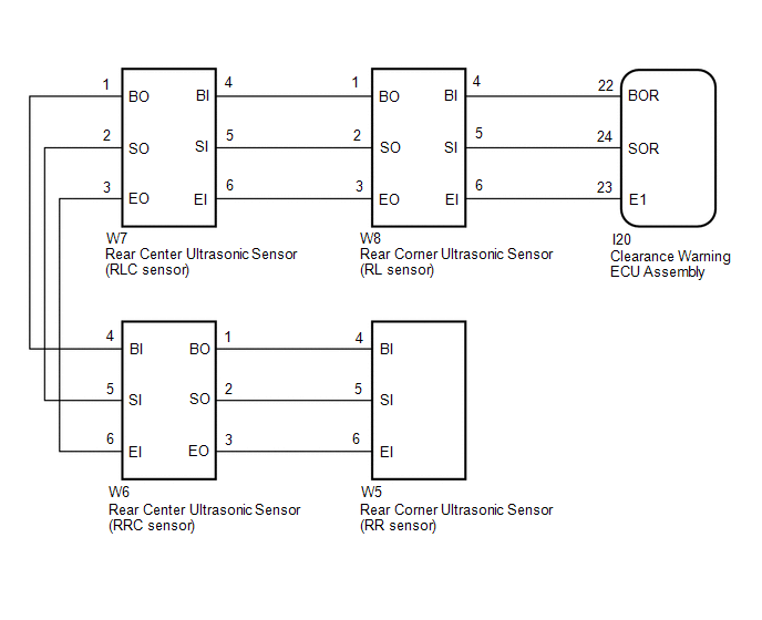
WIRING DIAGRAM
PROCEDURE
| 1. | INITIALIZE REAR CORNER ULTRASONIC SENSOR AND REAR CENTER ULTRASONIC SENSOR |
(a) Initialize the rear corner ultrasonic sensor (RL and RR sensor) and rear center ultrasonic sensor (RLC and RRC sensor).
Click here .gif)
|
.gif)
| 2. | CHECK DTC OUTPUT (C1AED) |
(a) Check for DTCs.
Click here
(b) Clear the DTCs.
Click here
(c) Recheck for DTCs.
Click here
| Result | Proceed to |
|---|---|
| No DTCs are output | A |
| DTC C1AED is output | B |
| A | .gif) | USE SIMULATION METHOD TO CHECK |
|
| 3. | CHECK HARNESS AND CONNECTOR (CLEARANCE WARNING ECU ASSEMBLY - REAR CORNER ULTRASONIC SENSOR [RL SENSOR]) |
(a) Disconnect the I20 clearance warning ECU assembly connector.
(b) Disconnect the W8 rear corner ultrasonic sensor (RL sensor).
(c) Measure the resistance according to the value(s) in the table below.
Standard Resistance:
| Tester Connection | Condition | Specified Condition |
|---|---|---|
| I20-22 (BOR) - W8-4 (BI) | Always | Below 1 Ω |
| I20-24 (SOR) - W8-5 (SI) | Always | Below 1 Ω |
| I20-23 (E1) - W8-6 (EI) | Always | Below 1 Ω |
| I20-22 (BOR) or W8-4 (BI) - Body ground | Always | 10 kΩ or higher |
| I20-24 (SOR) or W8-5 (SI) - Body ground | Always | 10 kΩ or higher |
| I20-23 (E1) or W8-6 (EI) - Body ground | Always | 10 kΩ or higher |
| NG | | REPAIR OR REPLACE HARNESS OR CONNECTOR |
|
| 4. | CHECK HARNESS AND CONNECTOR (REAR CORNER ULTRASONIC SENSOR [RL SENSOR] - REAR CENTER ULTRASONIC SENSOR [RLC SENSOR]) |
(a) Disconnect the W8 rear corner ultrasonic sensor (RL sensor).
(b) Disconnect the W7 rear center ultrasonic sensor (RLC sensor)
(c) Measure the resistance according to the value(s) in the table below.
Standard Resistance:
| Tester Connection | Condition | Specified Condition |
|---|---|---|
| W8-1 (BO) - W7-4 (BI) | Always | Below 1 Ω |
| W8-2 (SO) - W7-5 (SI) | Always | Below 1 Ω |
| W8-3 (EO) - W7-6 (EI) | Always | Below 1 Ω |
| W8-1 (BO) or W7-4 (BI) - Body ground | Always | 10 kΩ or higher |
| W8-2 (SO) or W7-5 (SI) - Body ground | Always | 10 kΩ or higher |
| W8-3 (EO) or W7-6 (EI) - Body ground | Always | 10 kΩ or higher |
| NG | | REPAIR OR REPLACE HARNESS OR CONNECTOR |
|
| 5. | CHECK HARNESS AND CONNECTOR (REAR CENTER ULTRASONIC SENSOR [RLC SENSOR] - REAR CENTER ULTRASONIC SENSOR [RRC SENSOR]) |
(a) Disconnect the W7 rear center ultrasonic sensor (RLC sensor)
(b) Disconnect the W6 rear center ultrasonic sensor (RRC sensor).
(c) Measure the resistance according to the value(s) in the table below.
Standard Resistance:
| Tester Connection | Condition | Specified Condition |
|---|---|---|
| W7-1 (BO) - W6-4 (BI) | Always | Below 1 Ω |
| W7-2 (SO) - W6-5 (SI) | Always | Below 1 Ω |
| W7-3 (EO) - W6-6 (EI) | Always | Below 1 Ω |
| W7-1 (BO) or W6-4 (BI) - Body ground | Always | 10 kΩ or higher |
| W7-2 (SO) or W6-5 (SI) - Body ground | Always | 10 kΩ or higher |
| W7-3 (EO) or W6-6 (EI) - Body ground | Always | 10 kΩ or higher |
| NG | | REPAIR OR REPLACE HARNESS OR CONNECTOR |
|
| 6. | CHECK HARNESS AND CONNECTOR (REAR CENTER ULTRASONIC SENSOR [RRC SENSOR] - REAR CORNER ULTRASONIC SENSOR [RR SENSOR]) |
(a) Disconnect the W6 rear center ultrasonic sensor (RRC sensor).
(b) Disconnect the W5 rear corner ultrasonic sensor (RR sensor).
(c) Measure the resistance according to the value(s) in the table below.
Standard Resistance:
| Tester Connection | Condition | Specified Condition |
|---|---|---|
| W6-1 (BO) - W5-4 (BI) | Always | Below 1 Ω |
| W6-2 (SO) - W5-5 (SI) | Always | Below 1 Ω |
| W6-3 (EO) - W5-6 (EI) | Always | Below 1 Ω |
| W6-1 (BO) or W5-4 (BI) - Body ground | Always | 10 kΩ or higher |
| W6-2 (SO) or W5-5 (SI) - Body ground | Always | 10 kΩ or higher |
| W6-3 (EO) or W5-6 (EI) - Body ground | Always | 10 kΩ or higher |
| NG | | REPAIR OR REPLACE HARNESS OR CONNECTOR |
|
| 7. | INSPECT REAR CORNER ULTRASONIC SENSOR (RR SENSOR) |
(a) Remove rear corner ultrasonic sensor (RR sensor).
Click here
(b) Inspect the rear corner ultrasonic sensor (RR sensor).
Click here
| NG | | REPLACE REAR CORNER ULTRASONIC SENSOR (RR SENSOR) |
|
| 8. | INSPECT REAR CENTER ULTRASONIC SENSOR (RRC SENSOR) |
(a) Remove the rear center ultrasonic sensor (RRC sensor).
Click here
(b) Inspect the rear center ultrasonic sensor (RRC sensor).
Click here
| NG | | REPLACE REAR CENTER ULTRASONIC SENSOR (RRC SENSOR) |
|
| 9. | INSPECT REAR CENTER ULTRASONIC SENSOR (RLC SENSOR) |
(a) Remove the rear center ultrasonic sensor (RLC sensor).
Click here
(b) Inspect the rear center ultrasonic sensor (RLC sensor).
Click here
| NG | | REPLACE REAR CENTER ULTRASONIC SENSOR (RLC SENSOR) |
|
| 10. | INSPECT REAR CORNER ULTRASONIC SENSOR (RL SENSOR) |
(a) Remove the rear corner ultrasonic sensor (RL sensor).
Click here
(b) Inspect the rear corner ultrasonic sensor (RL sensor).
Click here
| NG | | REPLACE REAR CORNER ULTRASONIC SENSOR (RL SENSOR) |
|
| 11. | REPLACE REAR CORNER ULTRASONIC SENSOR (RR SENSOR) |
(a) Replace the rear corner ultrasonic sensor (RR sensor) with a known good one.
Click here
HINT:
All of the sensors are interchangeable. To confirm whether a sensor is functioning normally, switch it with a known good sensor from the other end of the vehicle.
|
| 12. | CHECK DTC OUTPUT (C1AED) |
(a) Clear the DTCs.
Click here
(b) Check for DTCs.
Click here
| Result | Proceed to |
|---|---|
| No DTCs are output | A |
| DTC C1AED is output | B |
| A | | END (REAR CORNER ULTRASONIC SENSOR [RR SENSOR] WAS DEFECTIVE) |
|
| 13. | REPLACE REAR CENTER ULTRASONIC SENSOR (RRC SENSOR) |
(a) Replace the rear center ultrasonic sensor (RRC sensor) with a known good one.
Click here
HINT:
All of the sensors are interchangeable. To confirm whether a sensor is functioning normally, switch it with a known good sensor from the other end of the vehicle.
|
| 14. | CHECK DTC OUTPUT (C1AED) |
(a) Clear the DTCs.
Click here
(b) Check for DTCs.
Click here
| Result | Proceed to |
|---|---|
| No DTCs are output | A |
| DTC C1AED is output | B |
| A | | END (REAR CENTER ULTRASONIC SENSOR [RRC SENSOR] WAS DEFECTIVE) |
|
| 15. | REPLACE REAR CENTER ULTRASONIC SENSOR (RLC SENSOR) |
(a) Replace the rear center ultrasonic sensor (RLC sensor) with a known good one.
Click here
HINT:
All of the sensors are interchangeable. To confirm whether a sensor is functioning normally, switch it with a known good sensor from the other end of the vehicle.
|
| 16. | CHECK DTC OUTPUT (C1AED) |
(a) Clear the DTCs.
Click here
(b) Check for DTCs.
Click here
| Result | Proceed to |
|---|---|
| No DTCs are output | A |
| DTC C1AED is output | B |
| A | | END (REAR CENTER ULTRASONIC SENSOR [RLC SENSOR] WAS DEFECTIVE) |
|
| 17. | REPLACE REAR CORNER ULTRASONIC SENSOR (RL SENSOR) |
(a) Replace the rear corner ultrasonic sensor (RL sensor) with a known good one.
Click here
HINT:
All of the sensors are interchangeable. To confirm whether a sensor is functioning normally, switch it with a known good sensor from the other end of the vehicle.
|
| 18. | CHECK DTC OUTPUT (C1AED) |
(a) Clear the DTCs.
Click here
(b) Check for DTCs.
Click here
| Result | Proceed to |
|---|---|
| No DTCs are output | A |
| DTC C1AED is output | B |
| A | | END (REAR CORNER ULTRASONIC SENSOR [RL SENSOR] WAS DEFECTIVE) |
| B | | REPLACE CLEARANCE WARNING ECU ASSEMBLY |
READ NEXT:
 Control Module Communication Bus "A" Off (U0073,U0155)
DESCRIPTION These DTCs are stored when the clearance warning ECU assembly cannot receive and recognize several signals via the CAN communication line. DTC No. Detection Item DTC Detection Condi
CAN Communication Failure (Message Registry) (U1000)
DESCRIPTION If DTC U1000 is stored frequently, duplicate the conditions that cause the problem symptoms and perform the inspection again even if the DTC is not output when rechecking for DTCs. DTC
No. 1 Clearance Warning Buzzer Circuit
DESCRIPTION This circuit consists of the No. 1 clearance warning buzzer and clearance warning ECU assembly. An ECU-excited type buzzer is used. The ECU operates the buzzers using a sound pattern that
SEE MORE:
Freeze Frame Data
FREEZE FRAME DATA CHECK FREEZE FRAME DATA (a) Connect the Techstream to the DLC3. (b) Turn the power switch on (IG). (c) Turn the Techstream on. (d) Enter the following menus: Body Electrical / Navigation System / Trouble Codes. Body Electrical > Navigation System > Trouble Codes (e) Select a
Installation
INSTALLATION CAUTION / NOTICE / HINT HINT:
Use the same procedure for the RH and LH sides.
The following procedure is for the LH side.
NOTICE:
Because the RH side flexible hose and LH side flexible hose are not interchangeable, verify the part number when installing the rear flexible hose
