Lexus NX: Headlight Swivel ECU LH Communication (B2410,B2411,B2424,B2425)
DESCRIPTION
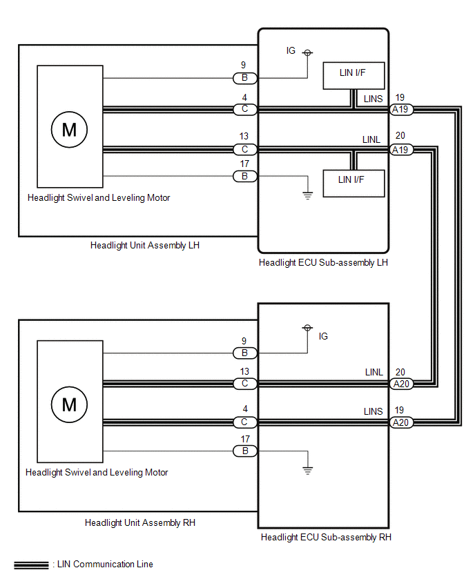
Each headlight ECU sub-assembly and headlight swivel and leveling motor communicate via LIN communication.
The headlight swivel and leveling motor operates according to power supplied and automatic headlight beam level control signals from its respective headlight ECU sub-assembly and sends its operating state to the headlight ECU sub-assembly.
| DTC No. | Detection Item | DTC Detection Condition | Trouble Area |
|---|---|---|---|
| B2410 | Headlight Swivel ECU LH Communication |
|
|
| B2411 | Headlight Swivel ECU RH Communication |
|
|
| B2424 | Headlight Beam Level Control Motor LH Lost Communication |
|
|
| B2425 | Headlight Beam Level Control Motor RH Lost Communication |
|
|
WIRING DIAGRAM
CAUTION / NOTICE / HINT
NOTICE:
If the headlight ECU sub-assembly LH has been replaced, it is necessary to synchronize the vehicle information and initialize the headlight ECU sub-assembly LH.
Click here .gif)
PROCEDURE
| 1. | CHECK FOR DTC |
(a) Clear the DTCs.
Click here
(b) Turn the power switch on (IG) and wait for at least 10 seconds or more.
(c) Check for DTCs.
Click here
OK:
DTC B2410, B2411, B2424 and B2425 are not outputs.
| Result | Proceed to |
|---|---|
| OK | A |
| NG (DTC B2410 is output) | B |
| NG (DTC B2411 is output) | C |
| NG (DTC B2410 and B2411 are output) | D |
| NG (DTC B2410 and B2424 are output) | E |
| NG (DTC B2411 and B2425 are output) | F |
| NG (DTC B2424 is output) | G |
| NG (DTC B2425 is output) |
| A | .gif) | USE SIMULATION METHOD TO CHECK |
| C | | GO TO STEP 3 |
| D | | GO TO STEP 6 |
| E | | GO TO STEP 10 |
| F | | GO TO STEP 11 |
| G | | GO TO AUTOMATIC HEADLIGHT BEAM LEVEL CONTROL SYSTEM |
|
.gif)
| 2. | CHECK HEADLIGHT ECU SUB-ASSEMBLY LH |
(a) Remove the headlight ECU sub-assembly LH as a unit with the connectors still connected.
Click here
(b) Disconnect the A20 headlight ECU sub-assembly RH connector.
(c) Measure the resistance according to the value(s) in the table below.
Standard Resistance:
| Tester Connection | Condition | Specified Condition |
|---|---|---|
| A20-19 (LINS) - C-4 | Always | Below 1 Ω |
| OK | | REPLACE HEADLIGHT UNIT ASSEMBLY LH |
| NG | | REPLACE HEADLIGHT ECU SUB-ASSEMBLY LH |
| 3. | CHECK HARNESS AND CONNECTOR (HEADLIGHT ECU SUB-ASSEMBLY LH - HEADLIGHT ECU SUB-ASSEMBLY RH) |
(a) Disconnect the A19 headlight ECU sub-assembly LH connector.
(b) Disconnect the A20 headlight ECU sub-assembly RH connector.
(c) Measure the resistance according to the value(s) in the table below.
Standard Resistance:
| Tester Connection | Condition | Specified Condition |
|---|---|---|
| A19-19 (LINS) - A20-19 (LINS) | Always | Below 1 Ω |
| NG | | REPAIR OR REPLACE HARNESS OR CONNECTOR |
|
| 4. | CHECK HEADLIGHT ECU SUB-ASSEMBLY LH (LINS TERMINAL SIGNAL OUTPUT) |
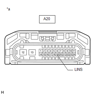
| *a | Front view of wire harness connector (to Headlight ECU Sub-assembly RH) |
(a) Disconnect the headlight ECU sub-assembly RH connector.
(b) Using the Techstream, check the waveform.
OK:
| Tester Connection | Switch Condition | Specified Condition |
|---|---|---|
| A20-19 (LINS) - Body ground | Power switch on (IG) | Pulse generation |
| NG | | REPLACE HEADLIGHT ECU SUB-ASSEMBLY LH |
|
| 5. | CHECK HEADLIGHT ECU SUB-ASSEMBLY RH |
(a) Remove the headlight ECU sub-assembly RH as a unit with the connectors still connected.
Click here
(b) Disconnect the A19 headlight ECU sub-assembly LH connector.
(c) Measure the resistance according to the value(s) in the table below.
Standard Resistance:
| Tester Connection | Condition | Specified Condition |
|---|---|---|
| A19-19 (LINS) - C-4 | Always | Below 1 Ω |
| OK | | REPLACE HEADLIGHT UNIT ASSEMBLY RH |
| NG | | REPLACE HEADLIGHT ECU SUB-ASSEMBLY RH |
| 6. | CHECK HEADLIGHT ECU SUB-ASSEMBLY RH |
(a) Disconnect the A20 headlight ECU sub-assembly RH connector.
(b) Clear the DTCs.
Click here
(c) Turn the power switch on (IG) and wait for at least 10 seconds or more.
(d) Check for DTCs.
Click here
| Result | Proceed to |
|---|---|
| DTC B2411 is output | A |
| DTC B2410 and B2411 are output | B |
| B | | GO TO STEP 8 |
|
| 7. | CHECK HEADLIGHT ECU SUB-ASSEMBLY RH |
(a) Remove headlight ECU sub-assembly RH.
Click here
(b) Reconnect the A20 headlight ECU sub-assembly RH connector.
(c) Clear the DTCs.
Click here
(d) Turn the power switch on (IG) and wait for at least 10 seconds or more.
(e) Check for DTCs.
Click here
| Result | Proceed to |
|---|---|
| DTC B2411 is output | A |
| DTC B2410 and B2411 are output | B |
| A | | REPLACE HEADLIGHT UNIT ASSEMBLY RH |
| B | | REPLACE HEADLIGHT ECU SUB-ASSEMBLY RH |
| 8. | CHECK HARNESS AND CONNECTOR (HEADLIGHT ECU SUB-ASSEMBLY LH - HEADLIGHT ECU SUB-ASSEMBLY RH) |
(a) Disconnect the A19 headlight ECU sub-assembly LH connector.
(b) Disconnect the A20 headlight ECU sub-assembly RH connector.
(c) Measure the resistance according to the value(s) in the table below.
Standard Resistance:
| Tester Connection | Condition | Specified Condition |
|---|---|---|
| A19-19 (LINS) or A20-19 (LINS) - Body ground | Always | 10 kΩ or higher |
| NG | | REPAIR OR REPLACE HARNESS OR CONNECTOR |
|
| 9. | CHECK HEADLIGHT ECU SUB-ASSEMBLY LH |
(a) Remove headlight ECU sub-assembly LH.
Click here
(b) Reconnect the A19 headlight ECU sub-assembly LH connector.
(c) Clear the DTCs.
Click here
(d) Turn the power switch on (IG) and wait for at least 10 seconds or more.
(e) Check for DTCs.
Click here
| Result | Proceed to |
|---|---|
| DTC B2410 is output | A |
| DTC B2410 and B2411 are output | B |
| A | | REPLACE HEADLIGHT UNIT ASSEMBLY LH |
| B | | REPLACE HEADLIGHT ECU SUB-ASSEMBLY LH |
| 10. | CHECK HEADLIGHT ECU SUB-ASSEMBLY LH |
(a) Replace the headlight ECU sub-assembly LH with a new one.
Click here
(b) Clear the DTCs.
Click here
(c) Turn the power switch on (IG) and wait for at least 10 seconds or more.
(d) Check for DTCs.
Click here
OK:
DTC B2410 and B2424 are not outputs.
| OK | | END (HEADLIGHT ECU SUB-ASSEMBLY LH WAS DEFECTIVE) |
| NG | | REPLACE HEADLIGHT UNIT ASSEMBLY LH |
| 11. | CHECK HEADLIGHT ECU SUB-ASSEMBLY RH |
(a) Replace the headlight ECU sub-assembly RH with a new one.
Click here
(b) Clear the DTCs.
Click here
(c) Turn the power switch on (IG) and wait for at least 10 seconds or more.
(d) Check for DTCs.
Click here
OK:
DTC B2411 and B2425 are not outputs.
| OK | | END (HEADLIGHT ECU SUB-ASSEMBLY RH WAS DEFECTIVE) |
| NG | | REPLACE HEADLIGHT UNIT ASSEMBLY RH |
READ NEXT:
 Headlight Swivel Motor LH (B2412,B2413)
DESCRIPTION The headlight ECU sub-assembly LH sends automatic headlight beam level control signals to each headlight swivel and leveling motor via LIN communication. Each headlight ECU sub-assembly an
Parts Location
PARTS LOCATION ILLUSTRATION *1 REAR HEIGHT CONTROL SENSOR SUB-ASSEMBLY LH *2 BRAKE BOOSTER WITH MASTER CYLINDER ASSEMBLY (SKID CONTROL ECU) *3 HEADLIGHT ASSEMBLY LH - HEADLIGHT ECU SUB
SEE MORE:
Blower Motor Circuit
DESCRIPTION The blower with fan motor sub-assembly is operated by signals from the air conditioning amplifier assembly. Blower motor speed signals are transmitted in accordance with changes in the duty ratio. WIRING DIAGRAM CAUTION / NOTICE / HINT NOTICE:
Inspect the fuses for circuits related t
Accumulator Low Pressure (C1256)
DESCRIPTION The accumulator pressure sensor is built into the brake actuator (brake booster with master cylinder assembly) and detects the accumulator pressure. The skid control ECU (brake booster with master cylinder assembly) turns on the brake warning light / red (malfunction) and brake warning l
