Lexus NX: Hybrid Vehicle Control Ecu
Components
COMPONENTS
ILLUSTRATION
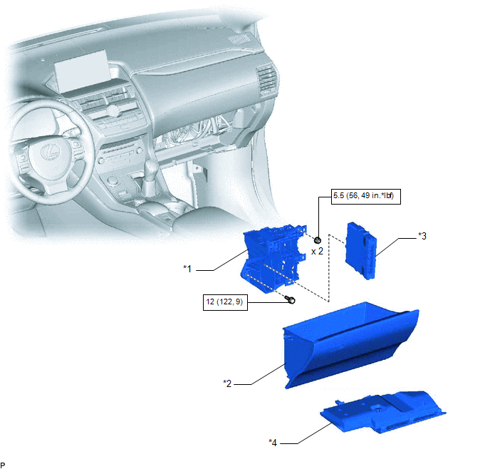
| *1 | ECU INTEGRATION BOX RH | *2 | GLOVE COMPARTMENT DOOR ASSEMBLY |
| *3 | HYBRID VEHICLE CONTROL ECU | *4 | NO. 2 INSTRUMENT PANEL UNDER COVER SUB-ASSEMBLY |
.png) | N*m (kgf*cm, ft.*lbf): Specified torque | - | - |
Removal
REMOVAL
PROCEDURE
1. PRECAUTION
NOTICE:
After turning the power switch is turned off, there may be a waiting time before disconnecting the auxiliary negative (-) battery terminal.
Click here .gif)
2. DISCONNECT CABLE FROM NEGATIVE AUXILIARY BATTERY TERMINAL
3. REMOVE NO. 2 INSTRUMENT PANEL UNDER COVER SUB-ASSEMBLY
Click here
4. REMOVE GLOVE COMPARTMENT DOOR ASSEMBLY
Click here
5. REMOVE ECU INTEGRATION BOX RH
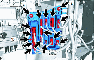
| *a | Nut |
| *b | Bolt |
(a) Disconnect the 13 connectors and clamp.
(b) Remove the 2 nuts, bolt and ECU integration box RH.
6. REMOVE HYBRID VEHICLE CONTROL ECU
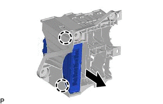
(a) Disconnect the 2 claws and remove the hybrid vehicle control ECU from the ECU integration box RH.
Installation
INSTALLATION
PROCEDURE
1. INSTALL HYBRID VEHICLE CONTROL ECU
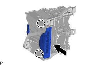
(a) Attach the 2 claws and install the hybrid vehicle control ECU to the ECU integration box RH.
2. INSTALL ECU INTEGRATION BOX RH
(a) Install the ECU integration box RH with the 2 nuts and bolt.
Torque:
for Nut :
5.5 N·m {56 kgf·cm, 49 in·lbf}
for Bolt :
12 N·m {122 kgf·cm, 9 ft·lbf}
(b) Connect the 13 connectors and clamp.
3. INSTALL GLOVE COMPARTMENT DOOR ASSEMBLY
Click here .gif)
4. INSTALL NO. 2 INSTRUMENT PANEL UNDER COVER SUB-ASSEMBLY
Click here
5. CONNECT CABLE TO NEGATIVE AUXILIARY BATTERY TERMINAL
6. INITIALIZATION AFTER RECONECTING AUXILIARY BATTERY TERMINAL
Click here
HINT:
When disconnecting and reconnecting the auxiliary battery, there is an automatic learning function that completes learning when the respective system is used.
Click here
READ NEXT:
 Components
COMPONENTS ILLUSTRATION *1 DECK FLOOR BOX LH *2 NO. 3 DECK BOARD SUB-ASSEMBLY *3 REAR DECK FLOOR BOX *4 NEGATIVE AUXILIARY BATTERY TERMINAL N*m (kgf*cm, ft.*lbf): Specified
Removal
REMOVAL PROCEDURE 1. PRECAUTION Click here 2. REMOVE SERVICE PLUG GRIP Click here 3. DRAIN COOLANT (for Inverter Coolant) Click here 4. DISCONNECT WIRE HARNESS (a) Disconnect the 4 wire harn
SEE MORE:
Components
COMPONENTS ILLUSTRATION *1 OIL FILTER CAP ASSEMBLY *2 O-RING *3 GASKET *4 OIL PAN DRAIN PLUG *5 OIL FILTER ELEMENT *6 OIL FILTER DRAIN PLUG *7 OIL FILLER CAP - - N*m (kgf*cm, ft.*lbf): Specified torque ● Non-reusable part
Parts Location
PARTS LOCATION ILLUSTRATION *A w/ Blind Spot Monitor System - - *1 FRONT TELEVISION CAMERA ASSEMBLY *2 REAR TELEVISION CAMERA ASSEMBLY *3 SIDE TELEVISION CAMERA ASSEMBLY RH *4 SIDE TELEVISION CAMERA ASSEMBLY LH *5 BRAKE BOOSTER WITH MASTER CYLINDER ASSEMBLY (SKID
